1 Cornerstone Electronics Technology and Robotics II - LAR
advertisement
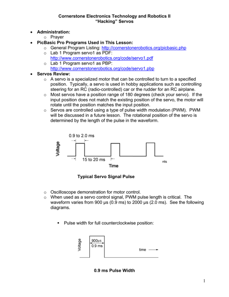
Cornerstone Electronics Technology and Robotics II “Hacking” Servos • • • Administration: o Prayer PicBasic Pro Programs Used in This Lesson: o General Program Listing: http://cornerstonerobotics.org/picbasic.php o Lab 1 Program servo1 as PDF: http://www.cornerstonerobotics.org/code/servo1.pdf o Lab 1 Program servo1 as PBP: http://www.cornerstonerobotics.org/code/servo1.pbp Servos Review: o A servo is a specialized motor that can be controlled to turn to a specified position. Typically, a servo is used in hobby applications such as controlling steering for an RC (radio-controlled) car or the rudder for an RC airplane. o Most servos have a position range of 180 degrees (check your servo). If the input position does not match the existing position of the servo, the motor will rotate until the position matches the input position. o Servos are controlled using a type of pulse width modulation (PWM). PWM will be discussed in a future lesson. The rotational position of the servo is determined by the length of the pulse in the waveform. Typical Servo Signal Pulse o Oscilloscope demonstration for motor control. o When used as a servo control signal, PWM pulse length is critical. The waveform varies from 900 µs (0.9 ms) to 2000 µs (2.0 ms). See the following diagrams. Pulse width for full counterclockwise position: 0.9 ms Pulse Width 1 Pulse width for center position: 1.5 ms Pulse Width Pulse width for full clockwise position: 2.0 ms Pulse Width • Continuous Rotation of a Servo: o By making a couple of modifications (hacking), we can fool the servo into continuous rotation in either direction. The steps to modify a Futaba 3003 servo are as follows: Remove the black screw that holds the horn on the servo rotating shaft. Remove the four screws from the back of the servo. Remove the back panel of the servo; then, gently remove the front panel, making sure none of the gears fall out. Remove three of the gears in order from the front of the panel; take a mental picture as to how the gears are aligned. The last gear that is against the housing can be removed by lifting the pin and gear at the same time. Place the gears in a row the way they came off the servo to help in reassembly. Cut the stop from the black potentiometer gear using a small back saw. Gently pull the servo control board out of the servo package. It is best to start by pushing the potentiometer shaft flush to the black servo housing. Then take a small screwdriver to pry at the corners to remove the control board. Carefully desolder the potentiometer from the servo control board. The desoldering tool from Electronix Express (part # 060848) works extremely well for this task. Measure the resistances of several ¼ watt 2.2 K resistors and pick two resistors with matching values; the 2.2K resistors mimic the center position of the discarded potentiometer. Install the two 2.2KΩ resistors in place of the potentiometer. Each resistor goes from an outer hole to the center hole of the three potentiometer holes, so the center hole has a lead from each of the two resistors inserted. Reassemble the servo. o Perform Hacking Servos LAB 1 – servo1.pbp 2 Electronics and Robotics II Hacking Servos LAB 1 – servo1.pbp • Purpose: The purpose of this lab is to acquaint the student with the operation and programming of a “hacked” hobby servo. • Apparatus and Materials: • 1 – Breadboard 1 – PIC16F88 Microcontroller 1 – 4.7 K, ½ Watt Resistor 1 – Futaba 3003 Servo Procedure: o Assemble the following circuit on a breadboard. o Now, open servo1.pbp and experiment with the PIC16F88 chip on your breadboard using test values between 100 and 200 for the pulse length. Find the setting around 150 that stops the servo from rotating. 3 • Challenge: o Pair up with another student and take two hacked servos and build a car that will navigate through the tape course on the table. Save the program as servo10.pbp. Here are the challenge conditions: Dead reckoning may be used to navigate the course. An LCD must display which direction the car is traveling, such as, forward, right, left, or backup. Create and call up subroutines for each direction of movement including backup. Do not use the word “reverse” since it is a reserved word in PicBasic Pro. See Appendix C in the green PicBasic Pro Compiler Manual by microEngineering Labs, Inc for a listing of all the reserved words in PBP. Electrical tape may be utilized to attach the servos to the car. Use Maxx Products International 2.5” light foam wheels mounted on round servo horn as the wheels. Wheels available at Colonial Hobby, Orlando, FL Use small Irwin Quick Clamp for front pivot. Sample Servo Driven Robotic Car 4

