TS1002/TS1004 Dual/Quad Op Amps
Demo Board
FEATURES
DESCRIPTION
The demo boards for the TS1002 and the TS1004 are
completely assembled and tested circuit boards that
can be used for evaluating the TS1002 and the
TS1004, respectively. The TS1002 and the TS1004
are the industry’s first and only dual and quad singlesupply, precision CMOS operational amplifiers fully
specified to operate at 0.8V while consuming less
than 0.6µA supply current per amplifier. Optimized for
ultra-long-life battery-powered applications, the
TS1002 and the TS1004 join the TS1001 operational
amplifier in the “NanoWatt Analog™” highperformance analog integrated circuits portfolio. Both
op amps exhibit a typical offset voltage of 0.5mV, a
typical input bias current of 25pA, and rail-to-rail input
and output stages. The TS1002 and the TS1004 can
operate from single-supply voltages from 0.65V to
2.5V.
0.65V to 2.5V Single-supply operation
AC-coupled Non-inverting and Inverting
configurations supplied
Fully Assembled and Tested
2mm x 2mm 2-layer demo board
The TS1002 and the TS1004 are fully specified at
VDD = 0.8V and over the industrial temperature range
(−40°C to +85°C). The TS1002 is available in PCBspace saving 8-lead MSOP surface-mount packages.
The TS1004 is available in a 14-pin TSSOP package.
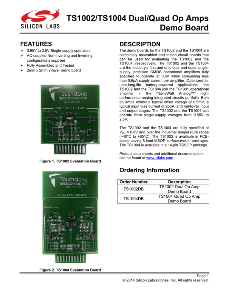
Figure 1. TS1002 Evaluation Board
Product data sheets and additional documentation
can be found at www.silabs.com.
Ordering Information
Order Number
TS1002DB
TS1004DB
Description
TS1002 Dual Op Amp
Demo Board
TS1004 Quad Op Amp
Demo Board
Figure 2. TS1004 Evaluation Board
Page 1
© 2014 Silicon Laboratories, Inc. All rights reserved.
TS1002/TS1004 Dual/Quad Op-Amps Demo Board
Description
Inverting Configuration
The TS1002 and the TS1004 demo boards provide
two configurations for evaluating the TS1002 dual
and the TS1004 quad operational amplifiers. A noninverting gain of +2 configuration is located on the
left-hand side of each board and an inverting gain of 1 configuration is located on the right-hand side of
each board. In both cases, the input to each circuit is
AC-coupled. The demo boards provide a re-biasing
scheme at one-half the power supply or VDD/2 for the
inverting configuration and at VDD/4 for the noninverting configuration.
In an inverting configuration, the circuit’s transfer
function is given by the following equation:
The TS1004 demo board provides resistor pads R3R10 and Jumpers B and C in order to access op
amps B and C. The default configuration for op amps
B and C is a unity-gain.The non-inverting inputs are
shorted to ground with 1Ω resistors on resistor pads
R5 and R8 and the outputs are connected to the
inverting inputs with 1Ω resistors on resistor pads R3
and R9.
In both the non-inverting and the inverting
configuration, the AC-coupling capacitor creates a
high pass filter. The resulting cut-off frequency, fC, is
given as:
fC=
ଵ
VOUT
VIN
=-
RX
RY
In this case, R3=RX=1MΩ and R6=RY=1MΩ on the
TS1002 demo board and R13=RX=1MΩ and
R14=RY=1MΩ on the TS1004 demo board. This
results in a signal gain of -1 with a circuit bandwidth
of 2kHz and an overall circuit bandwidth range of
1.6Hz to 2kHz.
Quick Start Procedures
Required Equipment
TS1002 or TS1004 demo board
DC Power Supply, Single or Dual Output
Function Generator
4-channel Oscilloscope
Two 1MΩ oscilloscope probes
ଶRC
Pin
In the non-inverting circuit on the TS1002 demo
board, R=R4=1MΩ and C=C2=0.1µF. In the inverting
case, R=R6=1MΩ and C=C3=0.1µF. In the noninverting circuit on the TS1004 demo board,
R=R17=1MΩ and C=C5=0.1µF. In the inverting case,
R=R14=1MΩ and C=C4=0.1µF. In both cases, these
component values generate a high-pass cut-off
frequency of 1.6Hz.
Default Configurations
Non-Inverting Configuration
In the non-inverting configuration, the circuit’s transfer
function is given by the following equation:
VOUT
VIN
RX
= 1+ RY
With R1=RX=2MΩ and R2=RY=2MΩ on the TS1002
demo board and R12=RX=2MΩ and R11=RY=2MΩ
on the TS1004 demo board, the circuit signal gain is
+2 with a circuit bandwidth of 2kHz. This results in an
overall circuit bandwidth range of 1.6Hz to 2kHz.
Page 2
Non-Inverting Inverting
Circuit
Circuit
VDD
VDD
VDD
VSS
GND
GND
INA, INB
VIN
VIN-1
OUTA, OUTB
VOUT
VOUT-1
Table 1. TS1002 Demo Board Test Points
Pin
Non-Inverting Inverting
Circuit
Circuit
VDD
VDD
VDD
VSS
GND
GND
INA, IND
VIN
VIN-1
OUTD, OUTD
VOUT
VOUT-1
Table 2. TS1004 Demo Board Test Points
Non-Inverting Configuration
In order to evaluate the TS1002 dual or TS1004 quad
operational
amplifiers
in
the
non-inverting
configuration, the following steps are to be performed:
1) Before connecting the DC power supply to the
demo board power test points, turn on the power
supply and set the DC voltage to 2.5V and then
turn it off.
TS1002/4-EVB Rev. 1.0
TS1002/TS1004 Dual/Quad Op-Amps Demo Board
2) Set the function generator frequency to 500Hz
and output level with a VOH = 1.45V and a
VOL = 1.05V. This sets the input signal swing to
400mVPP, centered at 1.25V.
3) In order to monitor the input and output signal,
select two channels on the oscilloscope and set
the vertical voltage scale and the coupling setting
on each channel to 200mV/DIV and AC,
respectively. Set the input and output vertical
position to +400mV and -200mV, respectively.
Set the horizontal time scale to 500µs/DIV.
4) Connect the positive terminal of the DC power
supply to test point VDD and the negative
terminal to test point GND on the TS1002 or
TS1004 demo board. For all other connections,
please refer to Table 1 and 2.
5) Connect the signal output of the function
generator to test point VIN on the TS1002 or
TS1004 demo board. Connect the ground
terminal to test point GND.
7) Turn on the power supply and check that the
power supply current is approximately 4.4µA for
the TS1002 demo board and 5.5µA for the
TS1004 demo board.
8) Turn on the function generator.
9) Observe the input and output signal. The output
signal is an amplified version of the input signal
with an output swing of approximately 800mVPP,
corresponding to a signal gain of two. Figure 5
shows what the input and output signal should
look like. The input signal is in yellow and the
output signal is in green.
Figure 4. TS1004 Amp ‘A’ Non-Inverting
Configuration
VOUT
VIN
200mV/DIV 200mV/DIV
Figure 3. TS1002 Amp ‘A’ Non-Inverting
Configuration
6) To monitor the input, connect the signal terminal
of one of the oscilloscope probes to test point VIN
on the TS1002 or TS1004 demo board. Connect
the ground terminal to test point GND. To monitor
the output, use the second probe to connect the
signal terminal to test point VOUT on the TS1002
or TS1004 demo board. Connect the ground
terminal to test point GND.
500µs/DIV
Figure 5. TS1002 and TS1004 Non-Inverting Configuration Input and Output signals
TS1002/4-EVB Rev. 1.0
Page 3
TS1002/TS1004 Dual/Quad Op-Amps Demo Board
Inverting Configuration
In order to evaluate the TS1002 dual or TS1004 quad
operational amplifiers in the inverting configuration,
the following steps are to be performed:
1) Before connecting the DC power supply to the
demo board, turn on the power supply and set
the DC voltage to 2.5V and then turn it off.
2) Set the function generator output frequency to
500Hz and output level with a VOH = 1.45V and a
VOL = 1.05V. This sets the input swing to
400mVPP, centered at 1.25V.
3) In order to monitor the input and output signal,
select two channels on the oscilloscope and set
the vertical voltage scale and the coupling setting
on each channel to 200mV/DIV and AC,
respectively. Set the input and output vertical
position to +400mV and -400mV, respectively.
Set the horizontal time scale to 500µs/DIV.
4) Connect the positive terminal of the DC power
supply to test point VDD and the negative
terminal to test point GND on the TS1002 or
TS1004 demo board. For all other connections,
please refer to Table 1 and 2.
Figure 6. TS1002 Amp ‘B’ Inverting Configuration
Page 4
5) Connect the signal output of the function
generator to test point VIN-1 on the TS1002 or
TS1004 demo board. Connect the ground
terminal to test point GND.
6) To monitor the input, connect the signal terminal
of one of the oscilloscope probes to test point
VIN-1 on the TS1002 or TS1004 demo board.
Connect the ground terminal to test point GND.
To monitor the output, use the second probe to
connect the signal terminal to test point VOUT-1
on the TS1002 or TS1004 demo board. Connect
the ground terminal to test point GND.
7) Turn on the power supply and check that the
power supply current is approximately 4.4µA for
the TS1002 demo board and 5.5µA for the
TS1004 demo board.
8) Turn on the function generator.
9) Observe the input and output signal. The output
signal is an inverted version of the input signal
with an output swing of approximately 400mVPP,
corresponding to a signal gain of negative one.
Figure 8 shows what the input and output signal
should look like. The input signal is in yellow and
the output signal is in green.
Figure 7. TS1004 Amp ‘D’ Inverting Configuration
TS1002/4-EVB Rev. 1.0
VOUT-1
200mV/DIV
VIN-1
200mV/DIV
TS1002/TS1004 Dual/Quad Op-Amps Demo Board
500µs/DIV
Figure 8. TS1002 and TS1004 Non-Inverting Configuration Input and Output signals
COMPONENT LIST
DESIGNATION
TS1002
QTY
C1, C2, C3
3
C4, C5
2
R8
1
R5
1
R3, R4, R6
3
R9, R10
2
R1, R2, R7
3
U1
1
VDD, VIN, VIN-1,
VOUT, VOUT-1
5
TS1002/4-EVB Rev. 1.0
DESCRIPTION
DESIGNATION
TS1004
QTY
DESCRIPTION
0.1µF ± 10%
capacitors (0805)
1µF ±10%
capacitors (0805)
665kΩ ± 1%
resistor (0805)
500kΩ ± 1%
resistor (0805)
1MΩ ± 1%
resistors (0805)
1.25MΩ ± 1%
resistors (0805)
2MΩ ± 1%
resistors (0805)
TS1002 Dual OpAmps
Test points
C1, C4, C5
3
C2, C3
2
R15
1
R18
1
R13, R14, R17
3
R1, R2
2
R11, R12, R16
3
U1
2
VDD, VIN, VIN-1,
VOUT, VOUT-1,
Out_B, Out_C
7
0.1µF ± 10%
capacitors (0805)
1µF ±10%
capacitors (0805)
665kΩ ± 1%
resistor (0805)
500kΩ ± 1%
resistor (0805)
1MΩ ± 1%
resistors (0805)
1.25MΩ ± 1%
resistors (0805)
2MΩ ± 1%
resistors (0805)
TS1004 Quad OpAmps
Test points
Page 5
TS1002/TS1004 Dual/Quad Op-Amps Demo Board
Figure 9. TS1002 Top Layer Component View
Figure 10. TS1002 Bottom Layer (GND) #1
Figure 11. TS1002 Bottom Layer (GND) #2
Page 6
TS1002/4-EVB Rev. 1.0
TS1002/TS1004 Dual/Quad Op-Amps Demo Board
Figure 12. TS1004 Top Layer Component
Figure 13. TS1004 Bottom Layer (G
Figure 14. TS1004 Bottom Layer (GND) #2
Silicon Laboratories, Inc.
400 West Cesar Chavez, Austin, TX 78701
+1 (512) 416-8500 ▪ www.silabs.com
Page 7
TS1002/4-EVB Rev. 1.0
Smart.
Connected.
Energy-Friendly
Products
Quality
Support and Community
www.silabs.com/products
www.silabs.com/quality
community.silabs.com
Disclaimer
Silicon Laboratories intends to provide customers with the latest, accurate, and in-depth documentation of all peripherals and modules available for system and software implementers
using or intending to use the Silicon Laboratories products. Characterization data, available modules and peripherals, memory sizes and memory addresses refer to each specific
device, and "Typical" parameters provided can and do vary in different applications. Application examples described herein are for illustrative purposes only. Silicon Laboratories
reserves the right to make changes without further notice and limitation to product information, specifications, and descriptions herein, and does not give warranties as to the accuracy
or completeness of the included information. Silicon Laboratories shall have no liability for the consequences of use of the information supplied herein. This document does not imply
or express copyright licenses granted hereunder to design or fabricate any integrated circuits. The products must not be used within any Life Support System without the specific
written consent of Silicon Laboratories. A "Life Support System" is any product or system intended to support or sustain life and/or health, which, if it fails, can be reasonably expected
to result in significant personal injury or death. Silicon Laboratories products are generally not intended for military applications. Silicon Laboratories products shall under no
circumstances be used in weapons of mass destruction including (but not limited to) nuclear, biological or chemical weapons, or missiles capable of delivering such weapons.
Trademark Information
Silicon Laboratories Inc., Silicon Laboratories, Silicon Labs, SiLabs and the Silicon Labs logo, CMEMS®, EFM, EFM32, EFR, Energy Micro, Energy Micro logo and combinations
thereof, "the world’s most energy friendly microcontrollers", Ember®, EZLink®, EZMac®, EZRadio®, EZRadioPRO®, DSPLL®, ISOmodem ®, Precision32®, ProSLIC®, SiPHY®,
USBXpress® and others are trademarks or registered trademarks of Silicon Laboratories Inc. ARM, CORTEX, Cortex-M3 and THUMB are trademarks or registered trademarks of
ARM Holdings. Keil is a registered trademark of ARM Limited. All other products or brand names mentioned herein are trademarks of their respective holders.
Silicon Laboratories Inc.
400 West Cesar Chavez
Austin, TX 78701
USA
http://www.silabs.com


