Class 1 ES-Key™ Super Node II
advertisement
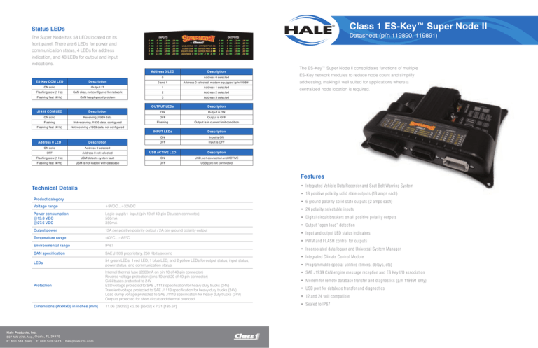
Class 1 ES-Key™ Super Node II Status LEDs Datasheet (p/n 119890, 119891) The Super Node has 58 LEDs located on its front panel. There are 6 LEDs for power and communication status, 4 LEDs for address indication, and 48 LEDs for output and input indications. Address 0 LED Description 0 Address 0 selected ES-Key COM LED Description 0 and 1 Address 0 selected, modem equipped (p/n 119891 ON solid Output 17 1 Address 1 selected Flashing slow (1 Hz) CAN okay, not configured for network 2 Address 2 selected Flashing fast (4 Hz) CAN has physical problem 3 Address 3 selected OUTPUT LEDs Description J1939 COM LED Description ON Output is ON ON solid Receiving J1939 data OFF Output is OFF Flashing Not receiving J1939 data, configured Flashing Output is in current limit condition Flashing fast (4 Hz) Not receiving J1939 data, not configured INPUT LEDs Description Address 0 LED Description ON Input is ON OFF Input is OFF ON solid Address 0 selected OFF Address 0 not selected USB ACTIVE LED Description Flashing slow (1 Hz) USM detects system fault ON USB port connected and ACTIVE Flashing fast (4 Hz) USM is not loaded with database OFF USB port not connected The ES-Key™ Super Node II consolidates functions of multiple ES-Key network modules to reduce node count and simplify addressing, making it well suited for applications where a centralized node location is required. Features • Integrated Vehicle Data Recorder and Seat Belt Warning System Technical Details • 18 positive polarity solid state outputs (13 amps each) Product category Voltage range +9VDC…+32VDC Power consumption @13.8 VDC @27.6 VDC Logic supply+ input (pin 10 of 40-pin Deutsch connector) 500mA 350mA Output power 13A per positive polarity output / 2A per ground polarity output Temperature range -40ºC…+85ºC Environmental range IP 67 CAN specification SAE J1939 proprietary, 250 Kbits/second LEDs 54 green LEDs, 1 red LED, 1 blue LED, and 2 yellow LEDs for output status, input status, power status, and communication status Protection Internal thermal fuse (2500mA on pin 10 of 40-pin connector) Reverse voltage protection (pins 10 and 20 of 40-pin connector) CAN buses protected to 24V ESD voltage protected to SAE J1113 specification for heavy duty trucks (24V) Transient voltage protected to SAE J1113 specification for heavy duty trucks (24V) Load dump voltage protected to SAE J1113 specification for heavy duty trucks (24V) Outputs protected for short circuit and thermal overload Dimensions (WxHxD) in inches [mm] Hale Products, Inc. 607 NW 27th Ave., Ocala, FL 34475 P: 800.533.3569 F: 800.520.3473 haleproducts.com 11.06 [280.92] x 2.56 [65.02] x 7.31 [185.67] • 6 ground polarity solid state outputs (2 amps each) • 24 polarity selectable inputs • Digital circuit breakers on all positive polarity outputs • Output “open load” detection • Input and output LED status indicators • PWM and FLASH control for outputs • Incorporated data logger and Universal System Manager • Integrated Climate Control Module • Programmable special utilities (timers, delays, etc) • SAE J1939 CAN engine message reception and ES Key I/O association • Modem for remote database transfer and diagnostics (p/n 119891 only) • USB port for database transfer and diagnostics • 12 and 24 volt compatible • Sealed to IP67 Mounting and Dimensions All inputs and communication lines are located on the 40-pin Deutsch connector. Main logic power is supplied to the Super Node II through the 40-pin Deutsch connector (pins 10 and 20). The Super Node II is a water-tight unit (IP67) and is mounted using four 1/4” or M6 screws. The overall Mating connector: Deutsch DRC26-40SA BLACK Mating sockets: 0462-201-20141 Wire gauge: 20-24 AWG dimensions are (W x H x D, inches [millimeters]) 11.06” [280.92] x 2.56” [65.02] x 7.31” [185.67]. PIN CIRCUIT DESCRIPTION CIRCUIT DESCRIPTION 1 Input 23 Digital input – polarity selectable 21 Modem ring Modem communication 2 Input 21 Digital input – polarity selectable 22 Input 19 Digital input – polarity selectable ES-Key Addressing 3 Input 17 Digital input – polarity selectable 26 Input 15 Digital input – polarity selectable 4 Input 13 Digital input – polarity selectable 24 Input 11 Digital input – polarity selectable The Super Node’s ES-Key network address is 5 Input 9 Digital input – polarity selectable 25 Input 7 Digital input – polarity selectable 6 Input 5 Digital input – polarity selectable 26 Input 3 Digital input – polarity selectable 7 Input 1 Digital input – polarity selectable 27 ADDR 3 Addressing input (ground polarity) selected by connecting a ground wire to one of PIN the addressing inputs on the 40-pin connector 8 ADDR 1 Digital input – polarity selectable 28 CAN High J1939 CAN (pin 8, 27, or 37). Using this method of 9 CAN Low ES-Key CAN 29 CAN Shield ES-Key CAN 10 Supply (+) Module supply (+9VDC…+32VDC) 30 SER GND Serial communication harness-side addressing allows the Super 11 Input 22 Digital input – polarity selectable 31 Modem tip Modem communication Node to be swapped without having to reset the 12 Input 20 Digital input – polarity selectable 32 Input 18 Digital input – polarity selectable 13 Input 16 Digital input – polarity selectable 33 Input 14 Digital input – polarity selectable address on the new unit. 14 Input 12 Digital input – polarity selectable 34 Input 10 Digital input – polarity selectable 15 Input 8 Digital input – polarity selectable 35 Input 6 Digital input – polarity selectable 16 Input 4 Digital input – polarity selectable 36 Input 2 Digital input – polarity selectable 17 Input 0 Digital input – polarity selectable 37 ADDR 2 Addressing input (ground polarity) PIN 0 ADDRESS 1 2 3 8 OPEN GND OPEN OPEN 37 OPEN OPEN GND OPEN 27 OPEN OPEN OPEN GND CAN Low J1939 CAN 38 CAN Shield J1939 CAN CAN High ES-Key CAN 39 SER TX Serial communication 20 Supply (-) Module supply (vehicle ground) 40 SER RX Serial communication Output driver power is supplied through the two power connectors (6 AWG wire recommended). Power connector A supplies power for outputs 0–9 and the power connector B supplies power for outputs 10–17. Connections All outputs are located on the two 12-pin Deutsch connectors (gray and black). Mating connector: Mating sockets: Wedge lock: Wire gauge: 18 19 Mating connector: Mating sockets: Wedge lock: Wire gauge: Deutsch DT06-12SB BLACK 0462-201-16141 W12S 16-18 AWG Mating connector: Deutsch DTHD-06-1-4-S BLACK Mating sockets: 0462-203-04141 Wire gauge: 6 AWG Deutsch DT06-12SA GRAY 0462-201-16141 W12S 16-18 AWG PIN CIRCUIT DESCRIPTION FEATURES PIN CIRCUIT DESCRIPTION FEATURES 1 Output 7 Positive output (13A max) FLASH, DCB, OOLD 1 Output 17 Positive output (13A max) FLASH, DCB, OOLD 2 Output 1 Positive output (13A max) FLASH, DCB, OOLD 2 Output 11 Positive output (13A max) FLASH, DCB, OOLD 3 Output 6 Positive output (13A max) FLASH, DCB, OOLD 3 Output 16 Positive output (13A max) FLASH, DCB, OOLD 4 Output 5 Positive output (13A max) FLASH, DCB, OOLD 4 Output 15 Positive output (13A max) FLASH, DCB, OOLD 5 Output 2 Positive output (13A max) FLASH, DCB, OOLD 5 Output 12 Positive output (13A max) FLASH, DCB, OOLD 6 Output 3 Positive output (13A max) FLASH, DCB, OOLD 6 Output 14 Positive output (13A max) FLASH, DCB, OOLD 7 Output 4 Positive output (13A max) FLASH, DCB, OOLD 7 Output 13 Positive output (13A max) FLASH, DCB, OOLD 8 Output 8 Positive output (13A max) FLASH, DCB, OOLD 8 Output 18 Positive output (2A max) — 9 Output 22 Positive output (2A max) — 9 Output 19 Positive output (2A max) — 10 Output 23 Positive output (2A max) — 10 Output 20 Positive output (2A max) — 11 Output 9 Positive output (13A max) FLASH, DCB, OOLD 11 Output 21 Positive output (2A max) — 12 Output 0 Positive output (13A max) FLASH, DCB, OOLD 12 Output 10 Positive output (13A max) FLASH, DCB, OOLD FLASH – output flashing capable, DCB – digital circuit breaker feature, OOLD – output “open load” detection, PWM – output pulse width modulation (60% duty cycle, 400 Hz) CIRCUIT DESCRIPTION DRIVER PWR A Driver power for outputs 0–9 (+9VDC…+32VDC) DRIVER PWR B Driver power for outputs 10–17 (+9VDC…+32VDC)
