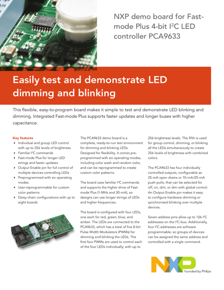
NXP demo board for Fastmode Plus 4-bit I2C LED
controller PCA9633
Easily test and demonstrate LED
Headline
dimming and blinking
This flexible, easy-to-program board makes it simple to test and demonstrate LED blinking and
dimming. Integrated Fast-mode Plus supports faster updates and longer buses with higher
capacitance.
Key features
4 Individual and group LED control
with up to 256 levels of brightness
4 Familiar I2C commands
4 Fast-mode Plus for longer LED
strings and faster updates
4 Output Enable pin for full control of
multiple devices controlling LEDs
4 Preprogrammed with six operating
modes
4 User-reprogrammable for custom
color patterns
4 Daisy-chain configurations with up to
eight boards
The PCA9633 demo board is a
complete, ready-to-run test environment
for dimming and blinking LEDs.
Designed for flexibility, it comes preprogrammed with six operating modes,
including color wash and random color,
and can be reprogrammed to create
custom color patterns.
The board uses familiar I2C commands
and supports the higher drive of Fastmode Plus (1-MHz and 30-mA), so
designs can use longer strings of LEDs
and higher frequencies.
The board is configured with four LEDs,
one each for red, green, blue, and
amber. The LEDs are connected to the
PCA9633, which has a total of five 8-bit
Pulse Width Modulators (PWMs) for
dimming and blinking the LEDs. The
first four PWMs are used to control each
of the four LEDs individually, with up to
256 brightness levels. The fifth is used
for group control, dimming, or blinking
all the LEDs simultaneously to create
256 levels of brightness with combined
colors.
The PCA9633 has four individually
controlled outputs, configurable as
25-mA open drains or 10-mA/25-mA
push-pulls, that can be selected for
off, on, dim, or dim with global control.
An Output Enable pin makes it easy
to configure hardware dimming or
synchronized blinking over multiple
devices.
Seven address pins allow up to 126 I2C
addresses on the I2C-bus. Additionally,
four I2C addresses are software
programmable, so groups of devices
can be assigned the same address and
controlled with a single command.
The board includes external 60-V FET drivers, which
can be connected to high-current, 350-mA LEDs. A
four-key keypad gives the user direct control over
the RGBA color mixing and light patterns.
Power can be supplied by the board’s 9-V battery
or via an external power connector. The RJ45
connector and cable can be used to daisy-chain
multiple boards, enabling the microcontroller on
one board to act as the master for up to seven
additional boards.
Reprogramming the microcontroller
Reprogramming the microcontroller requires an incircuit programmer (ICP), Flash Magic software (for
loading the microcontroller with compiled hex files),
and source code. For the ICP, NXP recommends the
USB-ICP-LPX9xx, available at www.teamfdi.com.
Flash Magic software is sponsored by NXP and is
available from the Embedded Systems Academy
Operating modes supported by the PCA9633 demo board
Mode 1
Auto Demonstration
Mode
Displays Mode 2 for 10 seconds, Mode 3 for 10 seconds,
and then repeats. Automatically selected at start-up.
Mode 2
Color Wash Mode
Continuously blends colors.
Mode 3
Random Color Mode Randomly shows different colors without blending
transitions.
Mode 4
User Color Mode
Displays user-selected colors. User can specify output of all
five PWMs.
Mode 5
Multiple-card Chase
Mode
Generates a chase pattern of multiple colors using the
PCA9633’s group-call feature and additional cards. Color
combinations can use two (amber/red), three (amber/red/
green), or four (amber/red/green/blue) colors. Supports up
to eight boards (master plus seven boards) connected via the
RJ45 jacks.
Mode 6
Output Enable
Control Mode
Demonstrates the Output Enable pin, which places the LED
outputs in High Z. Changes the LED diffuser color to purple
and blinks all LEDs at the same rate.
I2C BUS
RJ45
SW-5
SW-6
DIFFUSER
PULLUP
5V
REG
RJ45
(www.esacademy.com/software/flashmagic/).
PCA9633
Fast-mode Plus 4-bit I2C-bus LED controller with
individual 8-bit, 256-step PWMs for each LED plus
a fifth 8-bit, 256-step group PWM for dimming or
blinking combined colors.
P89LPC925
Flash microcontroller. Uses embedded firmware to
control the PCA9633. User-programmable via 10pin header and an external ICP-style programmer.
P82B96
Buffer for microcontroller. Supports the higher drive
of Fast-mode Plus, and enables off-board operation.
SW 1, 2, 3
Sets address pins to GND or VCC so up to
eight boards can be connected to the same
microcontroller.
+
-
60-V, 350-mA devices that use with high-brightness
LEDs.
RJ45
connector
Supplies additional cards with I2C-bus, power, and
Output Enable signals.
SW-8
FET
FET
FET
ON/OFF
9V
BATT
The PCA9633 demo board
5V
P82B96
Microcontroller
The PCA9633 demo board configured in Multiple-card Chase Mode (Mode 5)
www.nxp.com
© 2007 NXP N.V.
All rights reserved. Reproduction in whole or in part is prohibited without the prior written consent of the copyright owner. The
Date of release: January 2007
information presented in this document does not form part of any quotation or contract, is believed to be accurate and reliable and
Document order number: 9397 750 15907
may be changed without notice. No liability will be accepted by the publisher for any consequence of its use. Publication thereof
Printed in the USA
does not convey nor imply any license under patent- or other industrial or intellectual property rights.
PCA9633
Turns on power to 9-V battery.
FETs
FET
PCA9633
SW 8
ADDR
PCA9633
Sends power of 9-V battery over cables.
SW-7
R
PCA9633
LED
CTRLR
ICP
HDR
PCA9633
SW 7
SW1-3
PCA9633
Turns on bus pull-up resistors for master and
termination cards only.
LPC925
MICRO
3V
REG
CABLE
POWER
LEDs
OFF-BOARD LED SUPPORT
PCA9633
Sends Ouput Enable signal to other boards.
SW 5, 6
B
A
PUSHBUTTONS
PCA9633
SW 4
OE
MODE
Devices on the PCA9633 demo board
Description
SW-4
BFR
82B96
SEL
Device
G
I 2C


