Introduction to VSC HVDC
advertisement
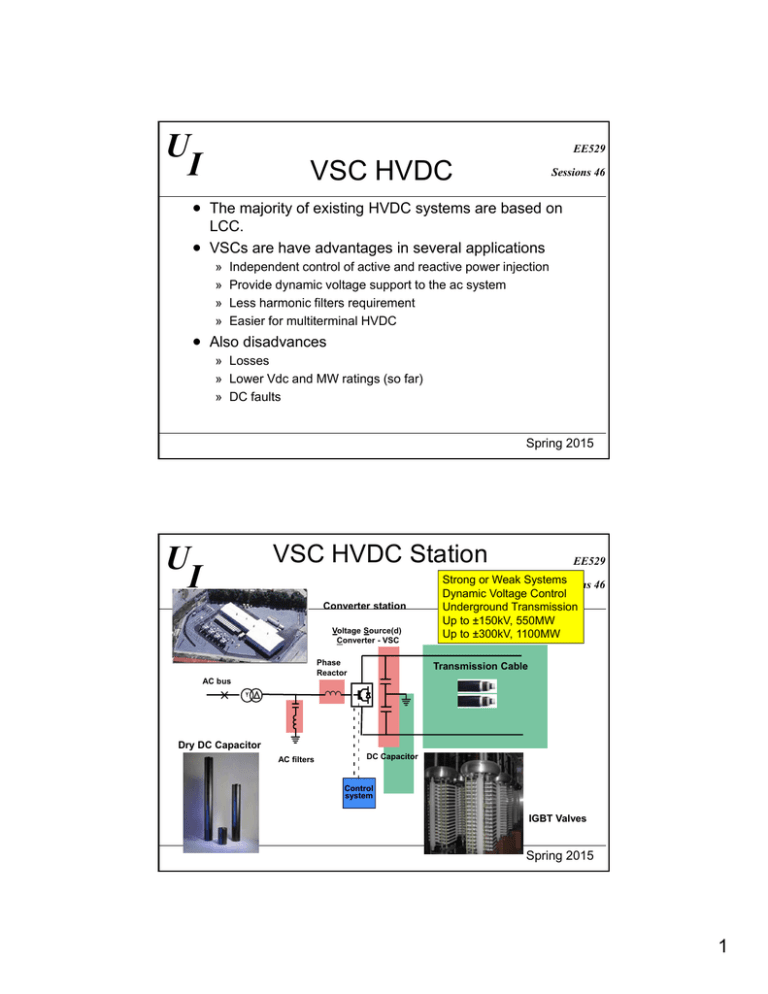
U I EE529 VSC HVDC Sessions 46 The majority of existing HVDC systems are based on LCC. VSCs are have advantages in several applications » » » » Independent control of active and reactive power injection Provide dynamic voltage support to the ac system Less harmonic filters requirement Easier for multiterminal HVDC Also disadvances » Losses » Lower Vdc and MW ratings (so far) » DC faults Spring 2015 VSC HVDC Station U I Converter station Voltage Source(d) Converter - VSC Phase Reactor EE529 Strong or Weak Systems Sessions 46 Dynamic Voltage Control Underground Transmission Up to ±150kV, 550MW Up to ±300kV, 1100MW Transmission Cable AC bus Dry DC Capacitor AC filters DC Capacitor Control system IGBT Valves Spring 2015 1 U I HVDC Converter Arrangements EE529 Sessions 46 Thyristor Module Conventional HVDC Single Double Quadruple Valve Valve Valve Thyristors Submodule Chip StakPak VSC Based HVDC IGBT Valve Stacks Cable Pair Spring 2015 U I Underground Cable Systems with VSC HVDC EE529 Sessions 46 Economic No distance limitation Full utilization – no reactive power Two cables v three cables for AC Land Light, flexible and simpler design Timely permitting No induced circulating currents Half the losses Easier transport and installation Sea Spring 2015 2 Underground Cable Systems (cont) U I Sessions 46 Reliability Land EE529 No cable overloads possible Dynamic reactive power support Congestion relief Isolate disturbances Share ROW without increasing exposure Black-start capability Sea Spring 2015 U I Control of VSC Based HVDC Transmission (most existing) EE529 Sessions 46 AC Line Voltages OPWM u DC1 uAC-ref1 - uAC1 u DC2 i i u uDC-ref1DC-ref2 - + AC voltage control qref1 + PWM internal current control uAC2 uAC-ref2 - DC voltage control AC voltage control + DC voltage control pref1 pref2 PWM internal current control q ref2 Principle control of HVDC-Light Spring 2015 3 U I Comparison of Reactive Power EE529 Sessions 46 Characteristics Spring 2015 7 Comparison of Reactive Power EE529 Sessions 46 Characteristics P-Q Diagram Active Power (p.u.) U I Operating Area Reactive Power (p.u.) HVDC VSC Operating Range 8 Spring 2015 4 U I Topology Options EE529 Sessions 46 Simplest three-phase VSC topology to build Consist of six IGBTs with six antiparallel diodes. Produce two voltage levels Use PWM switching technique to control dc voltage and ac phase voltage. Two-Level, Six-Pulse Bridge VSC Spring 2015 U I Multilevel Converters EE529 Sessions 46 Additional lGBTs/diodes Plus clamp diodes Produce three voltage levels (or more) Use PWM switching technique Less harmonics’ amplitudes More efficient than a Two-Level Bridge VSC Less device stress More complex and expensive than a Two-Level Bridge VSC Three-Level, Neutral Point Clamped VSC Spring 2015 5 U I EE529 Modular Multilevel ConverterSessions 46 Preferred VSC topology in new orders Consist of 100s of single phase VSC modules in series that switch in and out to control voltage magnitude and phase Half-Bridge Sub-Module Two Sub-Modules MMC Spring 2015 U I Advantages of MMC EE529 Sessions 46 Operate with lower switching frequency Scalable to higher voltage and power levels by changing the number of modules Lower harmonic distortion » Potential implement without filters Very high efficiency that can reach up to 99% Spring 2015 6 U I EE529 Sessions 46 What are MTDC systems? Advantages of Parallel configuration over series configuration » Transmission losses Disadvantages of Parallel configuration » Need DC circuit breaker to isolate faulted lines » Otherwise shut down entire system with AC protection Series MTDC System Configuration Potential for grids Parallel MTDC System Configuration Spring 2015 U I EE529 Sessions 46 VSCs using PWM and MMCs can control two variable independently Control was done in synchronous dq frame to improve response Inner current regulators and out control Current cross coupling term may have small effect Impact on ac systems Spring 2015 7

