10.2 Half-wavelength dipole
Basic theory
A dipole antenna, developed by Heinrich Rudolph Hertz around 1886 is an antenna with a center-fed driven element for transmitting or receiving radio
frequency energy. These antennas are the simplest practical antennas from a theoretical point of view. Typically, a dipole antenna is formed by two quarter
wavelength conductors or elements placed back to back for a total length of λ/2.
Fig. 10.2A.1 Wire model of dipole
A standing wave on an element of a length ~ λ/4 yields the greatest voltage differential, as one end of the element is at a node while the other element is at
an antinode of the wave. Assuming a sinusoidal distribution, the current impressed by this voltage differential is given by
I = I0 e jωt cos(kl).
( 10.2A.1 )
Here, I0 is the current in the maximum, denotes angular frequency and t time, k is wavenumber and l is the length of the dipole arm.
In the far-field zone, the electric field of a radiating electromagnetic wave is given by:
π
− jI0 cos( 2 cos θ) j ωt − kr
).
e (
sin θ
Eθ = 2πε cr
0
( 10.2A.2 )
Here, E is the respective component of the electric field, ε0 is the permitivity of vacuum, c is the speed of light in vacuum, r is the distance from the
observation point, is the angle measured from the dipole axis, and other symbols were already explained.
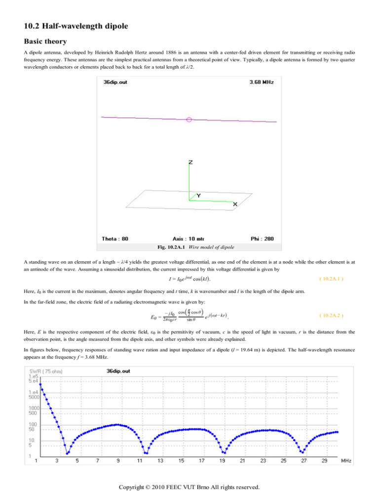
In figures below, frequency responses of standing wave ration and input impedance of a dipole (l = 19.64 m) is depicted. The half-wavelength resonance
appears at the frequency f = 3.68 MHz.
Copyright © 2010 FEEC VUT Brno All rights reserved.
Fig. 10.2A.2 Frequency response of standing wave ratio of half-wavelength dipole (l = 19.64 m)
Fig. 10.2A.3 Frequency response of input impedance of half-wavelength dipole (l = 19.64 m)
In fig. 10.2A.4, far field radiation pattern of a dipole in the half-wavelength resonance is depicted. The maximum radiation appears in the direction
perpendicular to the axis of the dipole. The antenna does not radiate in the axis of the dipole. Since the dipole is placed above the conducting plane, the
antenna radiates into a half-space only.
Fig. 10.2A.4 Far field radiation pattern of half-wavelength dipole above the conducting plane in the
height h = 20 m (l = 19.64 m, f = 3.68 MHz)
Copyright © 2010 FEEC VUT Brno All rights reserved.

