Form CP-THERMOCORE 1-FC (Version B)
�
Obsoletes CP-THERMOCORE 1-FC (Version A)
Replacement Kit for Discontinued Fan Control, Kit P/N 209184
Applies to all Reznor® Duct Furnaces and Packaged Systems
with a Thermocore® 1 Heat Exchanger
DANGER: This replacement kit is to be installed by a qualified service agency in accordance with
these instructions and in compliance with all codes and requirements of authorities having jurisdiction. Failure to follow instructions could result in death, serious injury, and/or property damage. The
qualified agency performing this work assumes responsibility for this installation.
Description/
Application
Components
Installation
Instructions
WARNING:
Improper installation,
adjustment, alteration,
service or maintenance
can cause property
damage, injury, or
death. Read the
instructions
thoroughly before
installing or servicing
this equipment.
The fan control used on Reznor heaters with a Thermocore® 1 heat exchanger has
been discontinued by the manufacturer. This kit is designed to replace the fan control and applies to all Reznor products using a Thermodisc 29T 12-32517 fan control
(Reznor P/N 10357).
Components of Kit P/N 209184
Qty
P/N
1
209186
Description
Wired Relay Assembly including Time Delay Relay, SPST, NO, 12S20-305131
1
209167
Relay Mounting Bracket
1
96426
#10 x 3/8" long Screw (attach relay to bracket)
1
209166
Fan Control, 60T82-314585 (125/90°F)
1
209169
Fan Control Shield Assembly
2
16354
Twist-on Wire Connector (orange)
1.Turn off the gas and the electric.
2.Remove the control access panel.
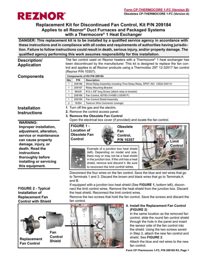
3.Remove the Obsolete Fan Control
Open the electrical box cover (if provided) and locate the fan control.
FIGURE 1 Location of
Obsolete Fan
Control
Obsolete
Fan
Control,
P/N 10357
Example of a junction box heat shield
(left). Depending on model and size,
there may or may not be a heat shield
in the junction box. If the unit has a heat
shield, remove and discard it. Be sure
to reconnect the limit control wires.
Limit
Control
Disconnect the four wires on the fan control. Save the blue and red wires that go
to Terminals 1 and 3. Discard the brown and black wires that go to Terminals A
and B.
If equipped with a junction box heat shield (See FIGURE 1, bottom left), disconFIGURE 2 - Typical
nect the limit control wires. Remove the heat shield from the junction box. Discard
the heat shield. Reconnect the limit control wires.
Installation of
Remove the two screws that hold the fan control. Save the screws and discard the
Replacement Fan
fan control.
Control with Shield
4.Install the Replacement Fan Control
(FIGURE 2)
In the same location as the removed fan
control, slide the round fan control shield
through the hole in the panel and insert
the sensor side of the fan control into
the shield. Using the two screws saved
Fan
in Step 3, attach the new fan control and
Control
shield. See FIGURE 2.
Replacement
Shield
Attach the blue and red wires to the new
Fan Control
fan control.
Form CP-Thermocore 1-FC, P/N 209185 R3, Page Installation
Instructions
(cont’d)
FIGURE
3 - Attach
the Relay
Bracket
and Relay
5.Install the Replacement Time Delay Relay (FIGURE 3)
Directly above the fan control, remove the two screws holding the patch plate that
covers a hole in the wall. Save the screws and discard the patch plate.
Position the relay mounting bracket over the hole. Orient the bracket so that the
large tab is at the top and the small tab is towards the bottom. Attach it using the
two screws from the patch plate. Use the screw from the kit to attach the relay to
the mounting bracket.
Relay
Bracket
Wired Relay Assembly
(wires not shown)
Select the appropriate wiring diagram in FIGURE 4 and follow it to connect the wiring. If needed, use the wire nuts for the relay wire connections.
DISCONNECT SWITCH
THERMOCORE I
FAN CONTROL
REPLACEMENT
KIT
LINE/1 OR 3/60
FIGURE 4A - If the fan
control is in the line
voltage circuit, use
the TOP Diagram in
Drawing 224201.
DWG. #224201 REV. #2
G
GRD
LIMIT
CONTROL
(SOME MODELS)
R or BL
BL
(NOTE 1)
REPLACEMENT
FAN CONTROL
CONTACTS
1
3
TIME DELAY
RELAY CONTACTS
1
3
FAN MOTOR OR
BLOWER RELAY
R
R
LINE VOLT
BR
24V
TIME DELAY
RELAY COIL
NOTE 1 - SOME UNITS USE TERMINAL STRIPS RATHER THAN WIRE CONNECTORS.
BK
NOTE 2 - INSTALL IN PLACE OF OLD FAN CONTROL HEATER.
NOTE 3 - LEAVE EXISTING LIMIT CONTROL INSTALLED AND WIRED ON UNIT.
H
H
(NOTE 2)
BR
GAS VALVE
FIGURE 4B - If the fan
control is in the 24V
control circuit, use the
BOTTOM Diagram in
Drawing 224201.
LINE VOLT
BR
R or BL
BL
REPLACEMENT
FAN CONTROL
CONTACTS
1
3
TIME DELAY
RELAY CONTACTS
1
3
BLOWER
RELAY/CONTACTOR
24V
R
(NOTE 1)
TIME DELAY
RELAY COIL
R
NOTE 1 - SOME UNITS USE TERMINAL STRIPS RATHER THAN WIRE CONNECTORS.
NOTE 2 - INSTALL IN PLACE OF OLD FAN CONTROL HEATER.
NOTE 3 - LEAVE EXISTING LIMIT CONTROL INSTALLED AND WIRED ON UNIT.
BK
H
H
(NOTE 2)
BR
GAS VALVE
6.Close the electrical box cover (if provided) and install the control access panel.
7.Turn on the electric and the gas. Check the unit for proper operation.
www.RezSpec.com; (800) 695-1901
Form CP-Thermocore 1-FC, Page ©2007 Thomas & Betts Corporation, All rights reserved.
Trademark Note: Reznor® is registered in the United States and other countries.
11/07 POD Form CP-Thermocore 1-FC (Version B.1)


