Practice Exam
advertisement
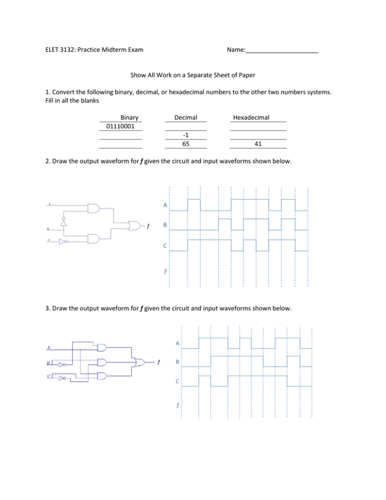
ELET 3132: Practice Midterm Exam Name:_____________________ Show All Work on a Separate Sheet of Paper 1. Convert the following binary, decimal, or hexadecimal numbers to the other two numbers systems. Fill in all the blanks Binary 01110001 Decimal -1 65 Hexadecimal 41 2. Draw the output waveform for f given the circuit and input waveforms shown below. f 3. Draw the output waveform for f given the circuit and input waveforms shown below. f 4, 5, 6. The following 3 logic expressions must be reduced to their minimum SOP form. One must be minimized using Boolean algebra, one must be minimized using Karnaugh maps, and one may be minimized in any way you want. You must show your work 4. f = A BC + AB C + ABC + BC f=_______ 5. f = AB + AB + A C f=_______ 6. f = A B C + A B C + ABC + ABC f=_______ Figure 1: VHDL Code #1 7. Sketch the Entity (the Black Box) and show the truth table for the VHDL code in Figure 1. f = ABC + AB + ABC + ABC Figure 2: Expression for problems 9-11 8. Implement the expression in Figure 2 using basic logic gates. Sketch the circuit. Do not minimize the expression. 9. Sketch the circuit for the expression shown in Figure 2 using an 8-to-1 multiplexer. 10. Sketch the circuit for the expression shown in Figure 2 using a 4-to-1 multiplexer. 11. Assume the waveforms in figure 3 are the signals on the inputs of the decoder and that the outputs are initially low. Draw the output waveforms on the diagram below. Figure 3: Input Waveforms for problems 12 12. Assume the waveforms in figure 4 are the signals on the inputs of the 4-bit adder and that the outputs are initially low. Draw the output waveforms on the diagram below. Figure 4: Input Waveforms for problems 12 13. Assume the waveforms in figure 5 are the signals on the S and R inputs of the flip-flop and that Q is initially low. Draw the Q output on the diagram below. Figure 5: Input Waveforms for problems 13 14. Assume the waveforms in figure 6 are the signals on the D input of the flip-flop and that Q is initially low. Draw the Q output on the diagram below. Figure 6: Input Waveforms for problems 14 15. Assume the waveform in figure 7 is the signal on the D input of the flip-flop and that Q is initially low. Draw the Q output on the diagram below. Figure 7: Input Waveforms for problems 15 16. Assume the waveform in figure 8 is the signal on the D input of the flip-flop and that Q is initially low. Draw the Q output on the diagram below. Figure 8: Input Waveforms for problems 16 17. Assume the waveform in figure 9 is the signal on the T input of the flip-flop and that Q is initially low. Draw the Q output on the diagram below. Figure 9: Input Waveforms for problems 17 18. Assume the waveforms in figure 10 are signals on the J and K inputs of the flip-flop and that Q is initially low. Draw the Q output on the diagram below. Figure 10: Input Waveforms for problems 18 19. What does the “HDL” stand for in the acronym “VHDL”: (V): Very High Speed Integrated Circuit: ________________ _____________________ ________________________
