T822 Thermostat
INSTALLATION INSTRUCTIONS
STEP 1. PREPARE FOR
INSTALLATION
3.
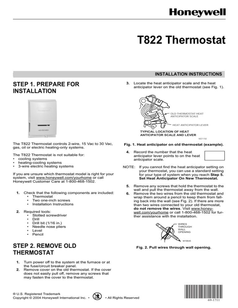
Locate the heat anticipator scale and the heat
anticipator lever on the old thermostat (see Fig. 1).
OLD THERMOSTAT HEAT
ANTICIPATOR SCALE
HEAT ANTICIPATOR LEVER
TYPICAL LOCATION OF HEAT
ANTICIPATOR SCALE AND LEVER
M21192
The T822 Thermostat controls 2-wire, 15 Vac to 30 Vac,
gas, oil or electric heating-only systems.
Fig. 1. Heat anticipator on old thermostat (example).
4.
The T822 Thermostat is not suitable for:
• cooling systems
• heating-cooling systems
• 3-wire electric heating systems
If you are unsure which thermostat model is right for your
system, visit www.honeywell.com/yourhome or call
Honeywell Customer Care at 1-800-468-1502.
NOTE: If you cannot find the heat anticipator setting on
your thermostat, you can use a standard setting
for your type of system when you reach Step 5.
Set Heat Anticipator On New Thermostat.
5.
1.
Check that the following components are included:
• Thermostat
• Two one-inch screws
• Installation Instructions
2.
Required tools:
• Slotted screwdriver
• Drill
• Drill bit (1/16 in.)
• Needle nose pliers
• Level
• Pencil
Record the number that the heat
anticipator lever points to on the heat
anticipator scale.
6.
Remove any screws that hold the thermostat to the
wall and pull the thermostat away from the wall.
Remove the two wires from the old thermostat and
wrap them around a pencil to keep them from falling back into the wall (see Fig. 2). If there are more
than two wires connected to your old thermostat,
do not remove the wires. Visit www.honeywell.com/yourhome or call 1-800-468-1502 for further assistance with the installation.
WIRES
THROUGH
WALL
OPENING
M19645
STEP 2. REMOVE OLD
THERMOSTAT
1.
2.
Fig. 2. Pull wires through wall opening.
Turn power off to the system at the furnace or at
the fuse/circuit breaker panel.
Remove cover on the old thermostat. If the cover
does not easily pull off, remove any screws that
may fasten the cover to the thermostat.
® U.S. Registered Trademark
Copyright © 2004 Honeywell International Inc. •
• All Rights Reserved
69-1711
T822 THERMOSTAT
MERCURY NOTICE
If this thermostat is replacing a control that
contains mercury in a sealed tube, do not place
the old thermostat in the trash. Contact your local
waste management authority for instructions
regarding recycling and proper disposal of this
control or of an old control containing mercury in
a sealed tube.
W
R
STEP 3. CONNECT WIRES TO NEW
THERMOSTAT
IMPORTANT
All wiring must comply with local building codes
and ordinances. If you are unsure about household wiring procedures, please call your local
heating/cooling contractor.
1.
2.
3.
4.
M19980
Remove the cover on the new thermostat. To
remove the cover, insert your thumb into the indentation on the side and pull the cover away from the
thermostat (see Fig. 3).
Loosen the R and W terminal screws on the back
of the new thermostat (see Fig. 4).
Remove the two wires from the pencil and attach
one wire to the R terminal and the other wire to the
W terminal (see Fig. 4 and 5).
Plug the hole in the wall with insulation to prevent a
warm or cool draft from affecting the operation of
the thermostat.
Fig. 4. R and W terminals on new thermostat.
FOR WRAPAROUND
INSERTION STRIP
7/16 IN. (11 MM)
M19648
Fig. 5. Wraparound and straight wiring connections.
STEP 4. MOUNT NEW
THERMOSTAT TO WALL
•40•50•60•
COVER
1.
2.
BACK OF
THERMOSTAT
3.
M19979
4.
Fig. 3. Remove cover on new thermostat.
69-1711
FOR STRAIGHT
INSERTION
STRIP
5/16 IN. (8 MM)
2
Position the thermostat on the wall. Place a level
on top of the thermostat and use a pencil to mark
the two mounting holes on the wall (see Fig. 6).
Move the thermostat to the side and drill the
mounting holes in the wall using a 1/16 in. drill bit
at the locations you marked.
Position the thermostat over the drilled holes and
loosely insert the mounting screws into the drilled
holes. Check the leveling of the thermostat and
tighten the mounting screws. Do not over tighten.
Remove styrofoam packing material that holds the
mercury switch in place during shipping.
T822 THERMOSTAT
2.
LEVEL
If you could not find a heat anticipator setting on
your old thermostat, use the setting listed in
Table 1 for your type of heating system.
Table 1. Heat Anticipator Setting.
MOUNTING
HOLE
DATE CODE
MODEL NO.
.1
.2 8
Heating System
.9
.7
.5
L
O
.25 N G E R .4
.3
Hot Water
.8
High Efficiency Warm Air (90% or
better)
.8
Gas or Oil Warm Air
.4
Electric
.3
3.
MOUNTING
HOLE
NOTE: MOVE TEMPERATURE LEVER IF
IT BLOCKS MOUNTING HOLE
M19981
Place the cover on the thermostat and turn the
power back on. If the heating system runs too long
to maintain a comfortable temperature, adjust heat
anticipator lever clockwise one scale mark (see Fig.
7). Do not adjust heat ancitipator below .3 Amps. If
the heating system needs to run longer to maintain
a comfortable temperature, adjust heat anticipator
lever counterclockwise, in the direction of the arrow,
one scale mark (see Fig. 7).
STEP 6. OPERATING NEW
THERMOSTAT
Fig. 6. Mount new thermostat to wall.
STEP 5. SET HEAT ANTICIPATOR
ON NEW THERMOSTAT
1.
Set the heat anticipator lever to the number that
you recorded in Step 2. Remove Old Thermostat,
sub-step 4 (see Fig. 7).
Adjust the temperature setting lever to your desired
setting. If it is too warm, lower the temperature setting. If it is too cool, raise the temperature setting.
STEP 7. ADJUSTABLE RANGE
STOPS
HEAT ANTICIPATOR
1.
.18
.2
.9
.7
.5
ONGE
.25
.3
L
R
1.
Heat Anticipator
Setting (Amps)
THIS POINT
SHOULD ALIGN WITH
HEAT ANTICIPATOR
SETTING
The T822 Thermostat comes equipped with adjustable range stops (see Fig. 8). The range stops are
factory set to allow for maximum adjustment of the
temperature lever. If you choose to limit the adjustment of the temperature lever, set range stops to
your desired setting.
.4
PLACE FINGER
HERE TO MOVE
LEVER
DATE CODE
MODEL NO.
.1
.2 8
.9
.7
.5
O
.25 N G E R .4
.3
L
DATE CODE
MODEL NO.
L
.18
.2
.9
.7
.5
O
.25 N G E R .4
.3
ADJUSTABLE
RANGE
STOPS
M22003
Fig. 8. Set adjustable range stops.
M19982
Fig. 7. Heat anticipator on new thermostat.
3
69-1711
T822 THERMOSTAT
IF YOU HAVE A PROBLEM
If. . .
Heating system
does not come on.
Customer Assistance
Then. . .
• Make sure the temperature
setting is above the room
temperature.
• Make sure the circuit breaker
is not tripped and reset it if
necessary.
• Make sure the power switch at
the equipment is in the On
position.
• Wait 5 minutes for the system
to respond.
Please read and follow the provided instructions for this
thermostat. For additional information, go to
www.honeywell.com/your home or call Honeywell
Customer Care at 1-800-468-1502.
Before calling, please have the following information
available:
• Thermostat model number and date code (refer to
Fig. 6 for the location of the model number and date
code).
• Type of heating system (for example: gas or oil; warm
air, hot water).
Heating system runs • Verify the thermostat is level.
too long to maintain • Adjust heat anticipator lever
a comfortable
clockwise one scale mark (see
temperature.
Fig. 7). Do not adjust heat
anticipator below .3 Amps.
Heating system
• Verify the thermostat is level.
needs to run longer • Adjust heat anticipator lever
to maintain a
counterclockwise, in the
comfortable
direction of the arrow, one
temperature.
scale mark (see Fig. 7).
Temperature lever • Adjust temperature range
cannot be set to the
stops (see Fig. 8).
highest and/or
lowest setting on the
temperature scale.
Automation and Control Solutions
Honeywell International Inc.
1985 Douglas Drive North
Golden Valley, MN 55422
69-1711
J.S. 2-04
Honeywell Limited-Honeywell Limitée
35 Dynamic Drive
Scarborough, Ontario
M1V 4Z9
Printed in U.S.A. on recycled
paper containing at least 10%
post-consumer paper fibers.
www.honeywell.com/yourhome


