Centrifugal Pumps: Casing, Prime Movers & Characteristics
advertisement

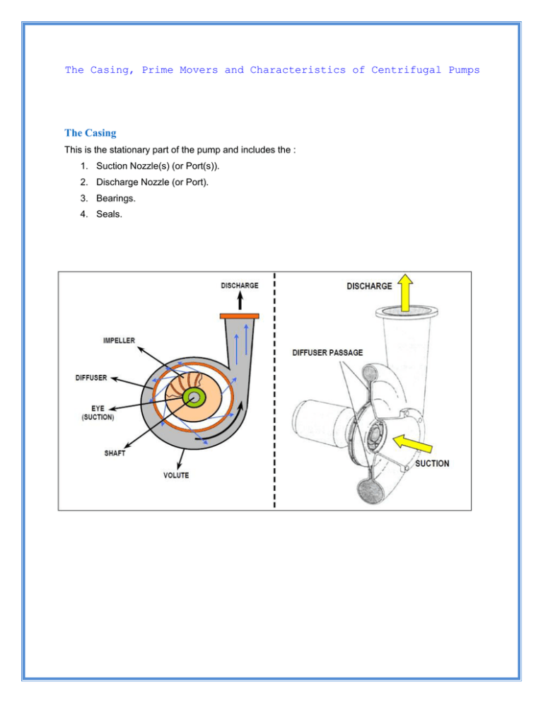
The Casing, Prime Movers and Characteristics of Centrifugal Pumps The Casing This is the stationary part of the pump and includes the : 1. Suction Nozzle(s) (or Port(s)). 2. Discharge Nozzle (or Port). 3. Bearings. 4. Seals. The casing of a multi-stage centrifugal pump is very similar to that of a multi-stage compressor having diaphragms with diffusers & return passages. However, as liquids are non-compressible, the stages do not become progressively narrower.The 'Volute' casing. This is named from the spiral shape of the casing which is so constructed to act as a collector for the liquid as it leaves the outer edge of the impeller vanes. The liquid at this point is at high velocity. As the liquid enters the volute, the velocity is decreased. This causes an increase in pressure which is the objective of the pump. (Increased pressure is increased energy). Prime Movers The prime movers for pumps are the devices used to drive them - whether they are rotating machines or otherwise. The types of prime mover used for modern pumps are : 1. Electric Motor. 2. Diesel (or petrol) engine. 3. Gas Turbine. 4. Steam Turbine. CHARACTERISTICS OF CENTRIFUGAL PUMPS Centrifugal pumps are specified by four characteristics. Capacity: This is defined as the quantity of liquid which is discharged from the pump in a given time. Capacity is expressed in 'm3/hr', 'gal/min', ..etc. The capacity of a pump is governed by the 'Head', the 'Speed' and the 'Size' of the pump. Total Head: The total head of a pump is the difference between the pump suction and discharge pressures - expressed in terms of metres or feet head : Suction Head : This is the vertical distance, in feet or metres, from the centreline of the pump to the level of liquid in the vessel from which the liquid is being pumped. If the liquid level is above the pump centreline, the suction head is positive. If below the centreline, the suction head is negative. Discharge Head: Is the discharge pressure of the pump, expressed in feet or metres of liquid. Total Head: = Discharge head -Suction head Power: This is the energy used by the pump in a given time. Its unit is 'Horsepower' (HP). 1 HP is equivalent to 0.746 kilowatt. (kW). Efficiency: This is a percentage measure of the pump's effectiveness in transferring the power used into energy added to the pumped liquid. The formula for calculation of efficiency is: Efficiency = (Output power)/(Input power)X 100% Pumps in industry, usually operate at 70% to 80% efficiency. The pump is taking suction from Tank 'A' and discharging to Tank 'B'. The Head (or height) of water in 'A' to the centre-line of the pump is 23 feet. This is called the 'SUCTION HEAD'. The discharge line inlet to 'B' is 50 feet above the pump centre-line. This is the 'DISCHARGE HEAD'. The 'TOTAL HEAD' is the difference between the two figures. This is 50 -23 = 27 feet. If the suction vessel is BELOW the pump centre line, the suction head will be a NEGATIVE figure. Using the formula for Static Head Pressure, we can find the suction and discharge pressures of the pump. (Both tanks are at atmospheric pressure). Suction pressure = 23 x 0.433 = 10 Psig. Discharge pressure = 50 x 0.433 = 21.7 Psig If a liquid other than water is used, the Specific Gravity of the liquid must be included in the above formula to obtain the pressures. E.g. If we use an oil with S.G. of 0.88, the pressures would be: Suction pressure = 23 x 0.433 x 0.88 = 8.8 Psig. Discharge pressure = 50 x 0.433 x 0.88 = 19.1 Psig Source : http://nprcet.org/e%20content/mech/FMM.pdf


