Over-Temperature protection for IGBT modules
advertisement

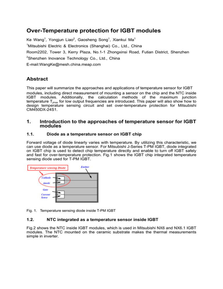
Over-Temperature protection for IGBT modules Ke Wang1, Yongjun Liao2, Gaosheng Song1, Xiankui Ma1 1 Mitsubishi Electric & Electronics (Shanghai) Co., Ltd., China Room2202, Tower 3, Kerry Plaza, No.1-1 Zhongxinsi Road, Futian District, Shenzhen 2 Shenzhen Inovance Technology Co., Ltd., China E-mail:WangKe@mesh.china.meap.com Abstract This paper will summarize the approaches and applications of temperature sensor for IGBT modules, including direct measurement of mounting a sensor on the chip and the NTC inside IGBT modules. Additionally, the calculation methods of the maximum junction temperature Tjmax for low output frequencies are introduced. This paper will also show how to design temperature sensing circuit and set over-temperature protection for Mitsubishi CM450DX-24S1. 1. 1.1. Introduction to the approaches of temperature sensor for IGBT modules Diode as a temperature sensor on IGBT chip Forward voltage of diode linearly varies with temperature. By utilizing this characteristic, we can use diode as a temperature sensor. For Mitsubishi J-Series T-PM IGBT, diode integrated on IGBT chip is used to detect chip temperature directly and enable to turn off IGBT safely and fast for over-temperature protection. Fig.1 shows the IGBT chip integrated temperature sensing diode used for T-PM IGBT. Fig. 1. Temperature sensing diode inside T-PM IGBT 1.2. NTC integrated as a temperature sensor inside IGBT Fig.2 shows the NTC inside IGBT modules, which is used in Mitsubishi NX6 and NX6.1 IGBT modules. The NTC mounted on the ceramic substrate makes the thermal measurements simple in inverter. Fig. 2. NTC inside IGBT module 2. 2.1. Using the NTC as a temperature sensor and OT protection Definition of the NTC The NTC is negative temperature coefficient thermistor, which is located on the same ceramic substrate as the IGBT and diode chips for Mitsubishi NX6 and NX6.1 IGBT modules. The IGBT chip temperature can be calculated by using a thermal model and measuring the temperature of NTC in steady state. 2.2. The approaches of calculating Tjmax for low output frequencies The NTC is designed for detection of a long term overload conditions, while it is not suitable for OT protection during short circuit condition or very short term overload. The principle of calculating the maximum junction temperature Tjmax under short pulse is shown as the follow. 2.2.1. How to calculate Tjave and Tjmax Refer to Fig.3, with the aid of the thermal resistances defined by reference points (h - heat sink, c - case, j – junction), the average junction temperature Tjave and the maximum junction temperature Tjmax are calculated using the following two equations Eq.1 and Eq.2. The average losses can be calculated using Mitsubishi’s Melcosim Ver.5.0.1 T jave = Th + Pave * Rth ( c -h ) + Pave * Rth ( j -c ) Eq.1 T j max Th + Pave * Rth( c -h ) + ΔT j -c _ max = TC + ΔT j -c _ max Eq.2 with Rth(j-c) as thermal resistance junction to case for the IGBT, Rth(c-h) as thermal resistance case to heat sink. 2.2.2. The methods of measuring Th and TC The heat sink temperature Th is measured underneath the module in a borehole of up to 2mm into the heat sink surface. The case temperature TC is measured directly beneath the chip via a drill hole in the heat sink as described in Fig.3. Besides, TC can also be measured by digging a hole of Ø0.8mm at just under the chip on the base plate of the modules as described in Fig.4, and this special sample can be customized by Mitsubishi. Fig. 3. Measuring points of Th and TC Fig. 4. Sample with thermo couple supplied by Mitsubishi 2.2.3. The principle of calculating ΔTj-c_max Under the actual operation for IGBT modules, the chips inside the modules are heated and cooled by the different amplitude and pulse duration in a PWM chopped current. The junction temperature Tjmax oscillates with the frequency of the output current. The principle of calculating the maximum temperature difference between junction and case ΔTj-c_max is shown in Fig.5. Fig. 5. (a) PWM chopped current (b) Input power pules (c) Power pulses separated into positive (d) Tj-c change caused by positive and and negative pulses and negative pulses (e) ΔTj-c composite Based on the above superposition principle, the following equation Eq.3 is used to calculate the temperature at the end and start of every pulse. ΔT( j -c ) [@ t 1] = P 1 * Rth( j -c ) [@ t 1] ΔT( j -c ) [@ t 2] = P 1 * Rth ( j -c ) [@ t 2] - P 1 * Rth ( j -c ) [@ t 2 - t 1] ΔT( j -c ) [@ t 3] = P 1 * Rth ( j -c ) [@ t 3] - P 1 * Rth ( j -c ) [@ t 3 - t 1] + P 2 * Rth ( j -c ) [@ t 3 - t 2] R th ( j - c ) τ i = ri [@ t ] = −t n τi ∑ r (1 - e ), t = t 1, t 2 - t 1, t 3 - t 2 i =1 Eq.3 i * ci The r and c can be easily extracted from a measured cooling curve of the IGBT modules, and the coefficients of τi and ri are provided in the datasheet. At output frequencies higher than 5Hz, an approximation of using rectangular shaped block to calculate the average losses. A simple method of calculating ΔTj-c_max, as a function of the output current frequency fO, is as the following formula Eq.4. - 1 2*fo *τ i n 1- e ΔT j -c _ max = 2 * Pav * ∑ ri 1 i =1 fo *τ i 1- e Eq.4 2.2.4. Temperature difference between junction and case for low output frequencies For example, using CM450DX-24S1 to develop 110kW two-level G/P inverter, the rated application conditions are that: VDC=540V, IO=210Arms, overload=315Arms, fc=3 kHz, Rg(on)= Rg(off)=5Ω.The average loss for upper or bottom IGBT is 306.53W. Based on this loss, ΔTj-c_max is calculated at low output frequencies (Table.1). ΔTj-c_max can be calculated using the following formula Eq.5. T j max TC + ΔT j −c _ max = TC + fcorr * Pave Eq.5 The factor fcorr can be obtained using the following formula Eq.6. fcorr (fo ) = ΔT j −c _ max Eq.6 Pave fo(Hz) ΔTj-c_max fcorr fo(Hz) ΔTj-c_max fcorr 0.1 60.37 5.08 2 53.30 5.75 0.2 60.21 5.09 3 50.06 6.12 0.3 59.97 5.11 4 47.44 6.46 0.4 59.66 5.14 5 45.29 6.77 0.5 59.31 5.17 6 43.51 7.05 0.6 58.92 5.20 7 42.00 7.30 0.7 58.52 5.24 8 40.70 7.53 0.8 58.11 5.27 9 39.57 7.75 0.9 57.69 5.31 10 38.57 7.95 1 57.27 5.35 Table.1. ΔTj-c_max and fcorr for low output frequencies For output frequencies above 10Hz, ΔTj-c_max can also be calculated using Melcosim Ver.5.0.1. 2.2.5. The differences between TNTC and TC For IGBT modules and heat sink, the below picture Fig.6 shows the thermal distribution and positions of different reference points for TNTC and TC. Fig. 6. Thermal distribution and positions of TNTC and TC Under constant average losses, TNTC and TC are slightly influenced by output frequencies, so the differences between TNTC and TC can be calculated with equation Eq.6. TNTC − TC = k * Pave Eq.7 TC = TNTC − k * Pave The factor k can be obtained by testing TNTC and TC under different Pave. 2.2.6. Using the NTC as over-temperature protection for IGBT modules Based on Eq.5 and Eq.6, Eq.7 is derived as the following. T j max TNTC + (fcorr − k ) * Pave Eq.8 Taking CM450DX-24S1 as an example, Tjmax has to be less than 150℃ to ensure SCSOA and RBSOA. TNTC ≤ 150°C − (fcorr − k ) * Pave Eq.9 Using the NTC temperature TNTC as OT protection, this OT protection value can be finally achieved by checking the relation of fcorr, k and Pave in software. 3. 3.1. Design details of temperature sensing circuit using diode and the NTC Using diode as a temperature sensor to design temperature sensing circuit To minimize the influence of the flowing current inside diode, a small current is employed.Fig.7 shows the application circuits for T-PM IGBT. Fig. 7. 3.2. (a) Using pull-up resistor (b) Using constant current Using the NTC as a temperature sensor to design temperature sensing circuit 3.2.1. The isolation considerations between the NTC and chips Since the NTC inside IGBT modules could be exposed to a high voltage level during the failure, a functional isolation for the NTC couldn’t be sufficient that reinforced isolation is often required in inverter. In accordance with EN 50178, additional isolation has to be done externally. 3.2.2. Design details of temperature sensing circuit Based on EN 50178, proper isolation levels have to be guaranteed for all parts of a piece of equipment that can be touched by a person. The isolation against high voltage can be achieved by an opto-coupler to make the NTC isolate from the control logic. To limit the self heating of the NTC by the flowing current, 3 to 4mA of flowing current are recommended. Fig.8 is a common sensing circuit. Fig. 8. Application circuit for temperature sensing 4. Conclusion The NTC is integrated inside IGBT modules as a temperature sensor to make the design of an accurate temperature measurement easy. Based on the relation of Tjmax and TNTC, it’s easy to set the OT protection point to protect IGBT modules. 5. References [1] Tetsuya Ueda, “Simple, Compact, Robust and High-performance Power module T-PM (Transfer-molded Power Module)”, in Proc. of the 22nd International Symposium on Power Semiconductor Devices & IC's, Hiroshima, Japan, June 2010, pp.47-50. [2] ON Semiconductor, “AN569/D:Transient Thermal Resistance-General Data and Its Use”


