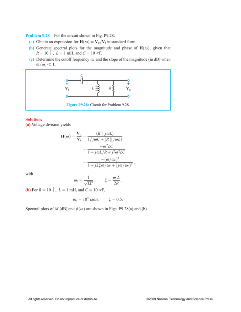
Problem 9.28 For the circuit shown in Fig. P9.28:
(a) Obtain an expression for H(ω ) = Vo /Vi in standard form.
(b) Generate spectral plots for the magnitude and phase of H(ω ), given that
R = 10 Ω, L = 1 mH, and C = 10 µ F.
(c) Determine the cutoff frequency ωc and the slope of the magnitude (in dB) when
ω /ωc ≪ 1.
C
+
+
L
Vi
_
R
Vo
_
Figure P9.28: Circuit for Problem 9.28.
Solution:
(a) Voltage division yields
H(ω ) =
Vo
(R k jω L)
=
Vi
1/ jωC + (R k jω L)
=
−ω 2 LC
1 + jω L/R + j2ω 2 LC
=
−(ω /ωc )2
,
1 + j2ξ ω /ωc + ( jω /ωc )2
with
1
ωc L
ωc = √
,
ξ=
.
2R
LC
(b) For R = 10 Ω, L = 1 mH, and C = 10 µ F,
ωc = 104 rad/s,
ξ = 0.5.
Spectral plots of M [dB] and φ (ω ) are shown in Figs. P9.28(a) and (b).
All rights reserved. Do not reproduce or distribute.
©2009 National Technology and Science Press
20
M (dB)
0
−20
−40
−60
−80
2
10
10
3
10
4
10
5
10
6
10
7
ω
ϕ (deg)
100
0
−100
10
2
10
3
10
4
10
5
10
6
10
7
ω
Figures P9.28(a) and (b)
(c) For ω /ωc ≪ 1,
ω
H(ω ) ≃ −
ωc
2
=⇒
All rights reserved. Do not reproduce or distribute.
slope = +40 dB/decade.
©2009 National Technology and Science Press
Problem 9.29 For the circuit shown in Fig. P9.29:
(a) Obtain an expression for H(ω ) = Vo /Vi in standard form.
(b) Generate spectral plots for the magnitude and phase of H(ω ), given that
R = 50 Ω and L = 2 mH.
(c) Determine the cutoff frequency ωc and the slope of the magnitude (in dB) when
ω /ωc ≪ 1.
R
+
+
L
Vi
_
R
Vo
_
Figure P9.29: Circuit for Problem 9.29.
Solution:
(a) Voltage division yields
H(ω ) =
Vo
(R k 1/ jω L)
=
Vi
R + (R k 1/ jω L)
jω L/R
1 + j2ω L/R
1
jω /ωc
,
=
2 1 + jω /ωc
=
with
ωc =
R
.
2L
(b) For R = 50 Ω and L = 2 mH,
ωc =
50
= 1.25 × 10⁴ rad/s.
2 × 2 × 10−3
Spectral plots of M [dB] and φ (ω ) are shown in Figs. P9.29(a) and (b).
All rights reserved. Do not reproduce or distribute.
©2009 National Technology and Science Press
0
M (dB)
−10
−20
−30
−40
−50
2
10
10
3
10
4
10
5
10
6
10
7
ω
ϕ (deg)
100
0
−100
10
2
10
3
10
4
10
5
10
6
10
7
ω
Figures P9.29(a) and (b)
(c) For ω /ωc ≪ 1,
H(ω ) ≃
jω
2ωc
=⇒
All rights reserved. Do not reproduce or distribute.
slope = +20 dB/decade.
©2009 National Technology and Science Press
Problem 9.30 For the circuit shown in Fig. P9.30:
(a) Obtain an expression for H(ω ) = Vo /Vi in standard form.
(b) Generate spectral plots for the magnitude and phase of H(ω ), given that
R = 50 Ω and L = 2 mH.
R
+
+
Vi
R
L
_
Vo
_
Figure P9.30: Circuit for Problem 9.30.
Solution:
(a) Voltage division yields
H(ω ) =
Vo
R
=
Vi
R + (R k jω L)
=
1 + jω L/R
1 + j2ω L/R
=
1 + jω /ωc1
,
1 + jω /ωc2
with
R
= 2.5 × 10⁴ rad/s,
L
ωc
ωc2 = 1 = 1.25 × 10⁴ rad/s.
2
ωc1 =
(b) Spectral plots of M [dB] and φ (ω ) are shown in Figs. P9.30(a) and (b).
Sections 9-6 and 9-7: Active Filters
Problem 9.31 For the op-amp circuit of Fig. P9.31:
(a) Obtain an expression for H(ω ) = Vo /Vs in standard form.
(b) Generate spectral plots for the magnitude and phase of H(ω ), given that
R1 = 1 kΩ, R2 = 4 kΩ, and C = 1 µ F.
(c) What type of filter is it? What is its maximum gain?
R2
_
+
R1
Vs
C
+
+
_
Vo
_
Figure P9.31: Circuit for Problem 9.31.
Solution:
R2
I2
I1
Vn
In = 0
Vp
R1
Vs
C
_
+
+
+
_
Vo
_
(a)
Vp = Vn = Vs
I1 + I2 = 0,
or equivalently,
Vs
Vs − Vo
+
= 0,
1
R2
R1 + j ω C
which leads to
H(ω ) =
Vo 1 + jω (R1 + R2 )C
=
Vs
1 + jω R1C
=
with
ωc1 =
1 + jω /ωc1
,
1 + jω /ωc2
1
,
(R1 + R2 )C
All rights reserved. Do not reproduce or distribute.
ωc2 =
1
.
R1C
©2009 National Technology and Science Press
(b) For R1 = 1 kΩ, R2 = 4 kΩ, and C = 1 µ F,
ωc1 = 200 rad/s,
ωc2 = 1000 rad/s.
Spectral plots are shown in Figs. 9.31(b) and (c).
15
M (dB)
10
5
0
1
10
10
2
10
3
10
4
10
5
10
6
ω
ϕ (deg)
100
0
−100
10
1
10
2
10
3
10
4
10
5
10
6
ω
Figures P9.31(b) and (c)
(c) It is a high-pass filter. For ω ≫ ωc2 ,
H(ω ) ≃
ωc2
= 5.
ωc1
Hence, maximum gain = 20 log 5 ≃ 14 dB.
All rights reserved. Do not reproduce or distribute.
©2009 National Technology and Science Press
Problem 9.35 For the op-amp circuit of Fig. P9.35:
(a) Obtain an expression for H(ω ) = Vo /Vs in standard form.
(b) Generate spectral plots for the magnitude and phase of H(ω ), given that
R1 = 1 kΩ, R2 = 20 Ω, C1 = 5 µ F, and C2 = 25 nF.
(c) What type of filter is it? What is its maximum gain?
C2
R2
R1
C1
_
+
+
Vs _
+
Vo
_
Figure P9.35: Circuit for Problem 9.35.
Solution: This is basically an inverting amplifier with a transfer function given by
H(ω ) =
Vo
Zf −(R2 k 1/ jωC2 )
=− =
Vs
Zs
R1 + 1/ jωC1
− jω R2C1
=
(1 + jω R1C1 )(1 + jω R2C2 )
=
− j(ω /ωc1 )
,
(1 + jω /ωc2 )(1 + jω /ωc3 )
with
1
1
=
= 104 rad/s,
R2C1 20 × 5 × 10−6
1
1
ωc2 =
= 3
= 200 rad/s,
R1C1 10 × 5 × 10−6
1
1
ωc3 =
=
= 2 × 10⁶ rad/s.
R2C2 20 × 25 × 10−9
ωc1 =
(b) Spectral plots are shown in Figs. P9.35(a) and (b).
All rights reserved. Do not reproduce or distribute.
©2009 National Technology and Science Press
−30
M (dB)
−40
−50
−60
−70
1
10
10
2
10
3
10
4
10
5
10
6
10
7
10
8
ω
ϕ (deg)
100
0
−100
10
1
10
2
10
3
10
4
10
5
10
6
10
7
10
8
ω
Figures P9.35(a) and (b)
(c) This is a bandpass filter with corner frequencies of 200 rad/s and 106 rad/s. In the
intermediate range, its maximum gain is approximately
R2
G ≃ 20 log
= 20 log 0.02 = −34 dB.
R1
All rights reserved. Do not reproduce or distribute.
©2009 National Technology and Science Press

