The Thin Convex Lens
advertisement

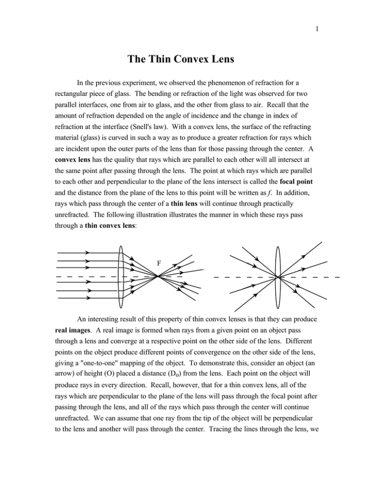
1 The Thin Convex Lens In the previous experiment, we observed the phenomenon of refraction for a rectangular piece of glass. The bending or refraction of the light was observed for two parallel interfaces, one from air to glass, and the other from glass to air. Recall that the amount of refraction depended on the angle of incidence and the change in index of refraction at the interface (Snell's law). With a convex lens, the surface of the refracting material (glass) is curved in such a way as to produce a greater refraction for rays which are incident upon the outer parts of the lens than for those passing through the center. A convex lens has the quality that rays which are parallel to each other will all intersect at the same point after passing through the lens. The point at which rays which are parallel to each other and perpendicular to the plane of the lens intersect is called the focal point and the distance from the plane of the lens to this point will be written as f. In addition, rays which pass through the center of a thin lens will continue through practically unrefracted. The following illustration illustrates the manner in which these rays pass through a thin convex lens: F An interesting result of this property of thin convex lenses is that they can produce real images. A real image is formed when rays from a given point on an object pass through a lens and converge at a respective point on the other side of the lens. Different points on the object produce different points of convergence on the other side of the lens, giving a "one-to-one" mapping of the object. To demonstrate this, consider an object (an arrow) of height (O) placed a distance (Do) from the lens. Each point on the object will produce rays in every direction. Recall, however, that for a thin convex lens, all of the rays which are perpendicular to the plane of the lens will pass through the focal point after passing through the lens, and all of the rays which pass through the center will continue unrefracted. We can assume that one ray from the tip of the object will be perpendicular to the lens and another will pass through the center. Tracing the lines through the lens, we 2 notice that they intersect on the other side. This is the position of the real image of the arrow. f Di O F I Do The distance from the lens to the real image is Di, the focal point F, and the image height is I. The real image (I) formed above is said to be inverted. The thin lens equation, which relates the object distance Do to the focal length f and the image distance Di, is: 1 1 1 f = Do + Di Object and image distances are considered positive if drawn as above. (The image distance would be negative if the image is not formed on the right of the lens.). Additionally the focal length (f) is positive for convex lenses. Using a property of similar triangles, the ratio of image height (I) to object height (O) is found equal to the ratio of image distance (Di) to object distance (Do). This ratio is called the magnification (M). Di I M = O = D o If the object is placed within the distance f of the lens, no real image will be formed. Instead, one will observe a virtual image which is the image seen when looking at the object through the lens. Repeating the ray-tracing procedure, you can observe how a virtual image is formed: 3 virtual image f I O F Do Di In this experiment, however, we will only be observing a real image created by light from a flashlight bulb, which is refracted through a thin convex lens. Procedure: You will be using the meter-stick as an optical bench. All of the optical components should be placed on the meter-stick perpendicular to it. 1. Place the flashlight bulb near the zero end of the bench scale. Connect it to the power supply and increase the voltage until the bulb shines moderately bright. 2. Place the screen about 75 cm from the bulb, and place the convergent lens between them. 3. Move the lens along the optical bench until a sharply defined image of the bulb is formed on the screen. Again move the lens until you see another image formed. There should be two places where the image appears. Note that for one M>1 while for the other M<1. 4. Now, carefully return the lens to the position which produced the first image. Record the object distance Do, the image distance Di. (Note: Do or Di will be the difference between the lens' position and the object or screen's position, respectively.) Use a ruler to measure the image size I and the object size O, and record these values also. 5. Repeat step 4 for the other lens position which produced the sharp image. Analysis: Use the data collected above to determine the focal length of the lens. You should get two values for the focal length. Use the distance ratios to determine the magnification of each real image. 4 Use the ruler to draw ray diagrams (like the one for the real image above) for each of the configurations which produced a sharp image. Conclusions: 1. Summarize your results for this experiment. 2. Are the two values for the focal length similar? Is this what you expected? Do the theoretical magnifications equal the ratio of object to image sizes? 3. Why do you think there are two positions of the lens which produce a sharp image? 4. If the screen and the object were located a distance of 4f apart, would there be two positions which produced sharp images? Why? Error Analysis: Describe major sources of error in this experiment. 5 The Thin Convex Lens Name:___________________Section:_________ Abstract: Image One: Data: Object Distance Do = Image Distance Di = Calculations: Calculate the focal length of the lens. Calculate the magnification of the image. Diagram: Image Two: Object Size O= Image Size I= 6 Data: Object Distance Do = Image Distance Di = Object Size O= Image Size I= 7 Calculations: Calculate the focal length of the lens. Calculate the magnification of the image. Diagram: Conclusions: (Use back if necessary) Error Analysis:


