PH Briquette Machine Operating Instructions
advertisement
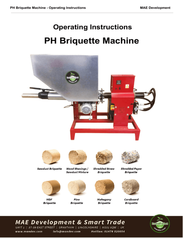
PH Briquette Machine - Operating Instructions MAE Development Operating Instructions PH Briquette Machine 1 PH Briquette Machine - Operating Instructions MAE Development Health and Safety Safety at work The person responsible for the machine must ensure that all applicable safety regulations are adhered to, in accordance with §4, 309/2006 Sb. Qualified personnel for assembly, disassembly, starting, handling, cleaning and regular maintenance must be appointed by the responsible personnel in order to ensure safety of persons and property. Precautionary measures must be carried out by the responsible personnel so no unauthorised person is able to operate the machine. The responsible personnel must ensure safe operation of the machine and regular maintenance and cleaning. The responsible personnel must carry out precautionary measures in order to prevent access to operation and maintenance area by unauthorised persons and children. The machine must be used for its designated purpose only, in accordance with manufacturer's conditions. Its design, mechanism and technical condition conforms to safety regulations. Only physically and mentally competent operators older than 18-years-old can handle the machine. They must be acquainted with its manual with a proof they've done so. The manual must be stored in a place accessible by the personnel. Operating staff using the machine must use personal protective aids, i.e. respirator mask to protect respiratory tract. Operating staff is responsible for checking the correct condition of the machine before it is operational, then in regular periods and after modifications of the machine. Operating staff must ensure that nobody approaches the working machine. Staff must shut down the machine in case of any danger. Operating staff must turn the machine off if he/she leaves it unattended for longer period. Operating staff is obliged to carry out visual checks of the machine and its basic maintenance. If the operating staff discovers a fault or a damage that could compromise operation safety and that cannot be undone by them, they must contact the responsible personnel immediately. If the machine is not in use for whatever reason, its electrical systems must be disconnected from the power supply by disconnecting the flexible lead's plug from the mains and also at the machine's end. The flexible lead must be stored in a place secured against unauthorised usage. It is essential to keep the safety markings, symbols and signs on the machine legible. The responsible personnel must restore their condition in case they are damaged or not legible anymore. Fire protection Beware! Harmful emissions may develop during a fire due to burning plastic, rubber and oil and therefore general applicable fire protection regulations must be adhered to. The machine is not equipped with fire extinguishers. Therefore the responsible personnel must secure the area where the machine is stored by appropriate and accredited fire protection means in sufficient number on visible places, protected against damage and misuse. They must be regularly checked and personnel must be familiarised with their handling. Electrical appliances must not be extinguished by water! There must be a powder, foam or CO2 fire extinguisher in the area and the personnel must be familiarised with their handling. If there is a water or foam extinguisher next to the appliance, it can only be used after the electricity is switched off. It is essential to regularly clean the cover surface of the electrical device or surface of the devices that are expected to get warmer, (surfaces of electric motors), from dust and other impurities in order to prevent decreased cooling efficiency of the electric motors. Electric appliances Only CUBP and CBU # 50/1978 Sb. qualified personnel knowing the device to an appropriate extent can operate the electrical appliance in accordance with CSN EN 50110-1 ed.2. Electrical system of the appliance is made according to the applicable regulation requirements and technical specifications, especially CSN EN 60 204-1 ed. 2 and related regulations. Electrical system of the appliance connects to the power supply 3/PE/A ~ 230/400 V, 50 Hz by flexible lead. The flexible lead to the electrical appliance must not lie on the ground without any protection against mechanical damage! If there is an additional protection in place with additional protective bonding in the area where the machine is installed, conductive dead parts of the machine must be connected to the protective system by a copper conductor 6 mm2 in diameter, connecting to the outer protective machine clamp marked by symbol #16 shown in section 1.1.3 of this manual. The responsible personnel is obliged to reinforce the realisation of regular revisions of the electrical appliance in set periods in accordance with §4, rule 309/2006 Sb. And CSN 33 1500 clause 3.1 and 3.6. 2 PH Briquette Machine - Operating Instructions MAE Development Prohibited activities DO NOT: To connect electrical system of the machine to the power supply if a protective part of the machine is dis-assembled or damaged (electrical system covers, covers on the potentially dangerous mechanical parts)! To let flexible lead lying on the ground without an appropriate protection against mechanical damage. To run the machine if there are people who may be exposed to a danger by being close to it. To dismantle protective covers when the machine is in operation and to deactivate protective and safety devices! To modify the construction of the machine. To carry out maintenance, cleaning and repairs if there is a possibility of all electrical circuits not being switched off. To pull the plug of the flexible lead from the socket by pulling the cable! To transfer the machine if it is connected to power supply by flexible lead! To feed the hopper by materials conflicting with the recommendations described in this manual, materials with higher humidity than 18%, materials with larger cutting length than 10 mm in one direction and especially materials different to wood. It is essential to bear in mind the possibility of the following risks that may arise when using the machine: Mechanical risks: Risk of an injury caused by a dropped dismantled parts of the machine during the maintenance and repairs or improper transfer. Risk of an injury caused by moving parts of the machine during removal of its protective covers. Risk of an injury caused by a dropped machine due to its inappropriate handling during transfer or in transit. Additional risks occurring when the machine is in use are described in the following sections and are marked by a symbol at each point. Electrical risks: Risk of direct or indirect contact with parts used for live electric current if the electrical system cover is removed or if the isolated parts are damaged. Risk of an injury by electric current touching inactive parts of the machine, due to the electrical system malfunction, due to the violation of the requirements described in points 4.3 and 5.4 of this manual. Risk of an injury by electric current when touching damaged parts of the flexible lead, (isolation of conductors, electric socket covers). Risk of an injury by electric current caused by damaged parts of the electric system (control devices, control circuit components). Hygienic risks: Risk of hearing apparatus injury by noise emissions above 85 dB (Laeq). The time-averaged emission level of acoustic pressure was measured at A -LpAeq, T = 70 dB. Risk of damaging person’s breathing apparatus during processing dry wood which causes increased amount of dust in the working area. 3 PH Briquette Machine - Operating Instructions MAE Development Table of contents page Health and Safety Introduction Signs usage and signs on the machine used in this manual Machine assignment Basic technical specification Additional technical specification Machine installation Key components of the machine Control panel Starting Stopping Temperature table Temperature settings Maintenance Final provisions Declaration of conformity Warranty List of repairs Notes List of the components 2-3 4 5 4 4 4 6 6 6 6 6 7 7 7 8 8 8 8 9 10 Technical and operating conditions of the PH series: Briquette material moisture limits: up to 18% Compacted briquette density: up to 700 kg/m3 Briquette length: 20-60 mm Maximal operating pressure: 8 t Hydraulic system max. operating temperature: 50° C Operating environment: 5°-25° C Briquette material: biomass waste, i.e. sawdust and shavings up to size of 10 mm with the specific weight ranging from 70-120 kg/m3 without any metallic and mechanical impurities with exception of wood. Technical Parameters Type: PH Power input: 3.42 kW Output: 10-15 kg/hour Weight: 124 kg Dimensions: 1.7 x 0.52 x 1 m Capacity of the hopper: 0.090 m3 Supply voltage: 230 V Machine Category: Private & Professional At the point of the machine operation, the equivalent of the acoustic pressure level A does not exceed 75 dB. The noise levels were tested in accordance with CSN ISO 3746: 1996 and CSN EN ISO 11202:1997 pursuant to NV 502/2000 Sb. Introduction The Operating Instructions apply to the hydraulic press system of the PH series . The Operating Instructions have been issued by the manufacturer and are consistent with the approved technical specifications which represent a binding document defining the requirements for briquette machine manufacture. The briquette material processed by the press comes out in a form of a cylindrical briquette, having the diameter of 50 mm and the length ranging from 20 - 60 mm. The briquette does not contain any binding agents and the compression is achieved solely by the pressure inside the cylindrical die, both through the resistance of the material itself and the increased temperature of the pressing unit. For the safety reasons, the PH models may be operated by the following personnel only: Installation staff: trained personnel of the Supplier Maintenance staff: trained personnel of the Customer with mechanical engineer qualifications Operators: trained personnel of the Customer 4 PH Briquette Machine - Operating Instructions MAE Development Machine signs Pictogram # Symbol Description BEWARE! There are areas of the electrical system underneath the covers marked with this pictogram. The electrical system must be turned off and secured before the covers can be taken off. 1 BEWARE! Areas where there are moving mechanical parts that may cause an injury are marked by this symbol. 2 4 Rotating direction of the electric motor Pictogram A Symbol Description Maintenance risk: Safety of people may be compromised if this requirement or advice is ignored. + text B + text Maintenance risk: An incident or an injury may occur if this requirement or advice is ignored. Machine risk: Safety of the machine may be compromised if this requirement or advice is ignored. C + text Pictogram # Symbol Manufacturer's label Description Label with basic technical parameters helping to identify and run the machine. Outer security clamp of the machine. The producer declares by this sign that the product conforms the requirements set forth in NV # 17/2003 Sb., NV # 616/2006 Sb., NV # 176/2008 Sb. and EU Directive associated with the product, i.e. 2006/95/EC, 2004/108/EC and 2006/42/EC. 5 PH Briquette Machine - Operating Instructions MAE Development Press machine installation The briquette machine is delivered on a pallet. All hydraulic and electrical parts are earthed, connected to the control panel and ready to use. Key Components Hopper, electric motor with a pump, hydraulic allocator, electric gearbox for feeding the hopper, die clamp, press unit, control panel, electric switchboard. Control Panel The heating control panel is located on the machine cover and it is set at the final temperature of 300°C by default. It is operated by on / off switch located below the display. The controls on the display can be used for changing the temperature setting. The actual temperature is shown in the upper part of the display, the pre-set temperature is displayed in its lower part. As soon as the machine is switched on by the main switch (See below), the operator has to wait until the chamber heats up fully (it may take a few minutes). The main switch is located on the motor. Once the protective cover is open, the machine can be switched on by pressing the green button and switched off either by pressing the red button or by shutting the cover. Starting the machine The machine is activated by pressing the main switch and the heating unit switch. Once the pre-set temperature is reached, the briquette operation can be started. The machine starts operating by itself after the main switch start-up. Hydro-system adjusts the pressure at each end and thus the movement of the cylinder is changed out of the die or other way into the pressure chamber. To produce a quality briquette, the press die clamp has to be adjusted, See the Figure on the left. The clamp must be either tightened or released according to the current briquette quality and the briquette material. The clamp can be tightened in small increments as long as the briquettes easily come out of the chamber. The clamp needs to be released in case the briquette doesn't come out of the die. By incremental adjusting of the clamp, high-quality briquettes can be obtained in a few cycles. A change in briquette material will require the clamp to be released and the adjustment process repeated. The recommended position of the clamp is 1-2 inches from the edge of the heating protective cover. The machine features a feeder which is installed inside the hopper. The feeder is activated by the main switch and works independently, so only replenishment of material is needed. The briquette operation is carried out by an operator in accordance with the instructions mentioned here-above. If the feeder stops without any apparent reason, you may have to change the fuse 1.25A. (Don’t use higher amperage rating.) The fuse protects the motor. Stopping the press machine manual - by turning the main switch off and disconnecting the power supply. 6 PH Briquette Machine - Operating Instructions MAE Development DO NOT: • put hands into the machine or otherwise prevent the individual components of the machine from operating, the source material replenishing process must be carried out with maximum care and appropriate measures must be taken to prevent clothing or body parts from being caught by the feeder. • put large objects into the hopper. • access the electric switchboard if the machine is connected to the power supply. • operate the machine in case of an apparent defect. • overfill the hopper or forcefully insert the material into the hopper • operate the machine at temperatures below 5°C • interfere with the machine design and modify it. All modifications must be approved by the Manufacturer. Recommended temperatures for the following materials: Material Mixture of pitch pine Softwood Hardwood Sawdust Melamine powder Blocked die temperature Recommende d temperature in °C From to 50 120 140 190 160 230 200 210 250 230 240 280 The temperature is set using the control panel. The 'SET' button must be pressed in order to get to the temperature settings. The temperature shown on the top row of the display can be changed by 'UP' and 'DOWN' buttons as needed. It is necessary to press the 'SET' button a couple of times to get the default screen on the control panel – the temperature is then confirmed and the heating should reach the desired level. Maintenance Maintenance must be carried out regularly. The briquette machine is to be shut down if evident defects appear and the operation must be stopped until the issues are fixed. Mechanical components The proper function of the machine requires an adequate distance to be maintained between the die clamp and the press machine body. The correct position of the clamp is 0-5 mm from the protective cover of the heating system. In order to avoid loose screws, all of them must be re-tightened regularly. If the main press roller scrapes against the press chamber, 6 nuts at the rear side of the machine are to be used for its alignment. Bear in mind, while centring the piston using the six nuts, that the gap between the rear end of the cylinder and the rear part of the press chamber should be 40mm. Hydraulic component Hydraulic hoses joints must be checked daily. The oil level must be checked regularly, at least once a month. The oil must be changed at least once a year. The machine uses hydraulic oil RENOLIN VG 46 or similar. Electrical component The electric switchboard must be kept clear of dust particles. All the maintenance and servicing is carried out while the machine is switched off (with no electric current supply to the machine). A visual check of the wire insulation is necessary as well. A general inspection of the machine in accordance with CSN EN 60204-1 Section 20 must be carried out at three-year interval. Any repairs of or interventions in machine wiring may be performed only by a competent person in accordance with relevant regulations. Any electric switchboard related work requires its disconnection from the power supply (the electric switchboard is under electrical current). 7 PH Briquette Machine - Operating Instructions MAE Development There is the heating control panel on the electric switchboard box, the heating ON/OFF switch starts the feeder as well. There is a 1.25A fuse in the panel – it is not to be replaced by a fuse of a different type. Final Provisions The manufacturer reserves the right to alter the specification of the components used due to potential changes of their suppliers. The general inspections of the electrical components must be carried out by a competent person in accordance with applicable legal regulations. The manufacturer's service centre must be notified of any defect which prevents smooth operation of the machine: Via exclusive importer and distributor MAE Development & Smart Trade IMPORTANT NOTICE: Press chamber blockage: In case there is a blockage in the press chamber, the following should be carried out: • the left over material needs to be removed from the hopper, • the temperature should be increased to the appropriate level (see the temperature table), • the normal briquette flow should be attempted after approx. 10 minutes, • if the first attempt is not successful, another one should be carried out several minutes later and repeated until the briquette comes out, • if the press chamber is blocked, the die clamp should be fully released, • the usual temperature should be set after the briquette causing the blockage is pressed out and normal flow of briquetting should continue. Buttons can be used on the automatic switchboard version (one at the top, one at the bottom of the switchboard) to control the switchboard manually and thus speed up the release process. 8 PH Briquette Machine - Operating Instructions MAE Development Declaration of CE Conformity Product: Briquette press PH15 7090950/2012 The Manufacturer declares that the product, used as instructed, is safe and all measures have been taken to ensure the conformity of the products placed on the market with their technical documentation, fundamental requirements set forth in 98/37 EC Directive issued by the European Parliament and Councils and with technical requirements of standards associated with the product. Terms and Conditions Please, see our website for details: http://www.maedev.com/terms/ List of repairs Date Work description Technician Supplier MAE Development & Smart Trade Ltd Unit 1, 37-39 East Street, Grantham, NG31 6QW, UK Tel.: 0044 1476 520054 ………………………..................................................... date & signature 9 PH Briquette Machine - Operating Instructions MAE Development Notes: 10 PH Briquette Machine - Operating Instructions MAE Development Ref. PR-R001 PR-R003 PR-R004 PR-E001 PR-E002 PR-E003 PR-E003a PR-E004 PR-E005 PR-E006 PR-E007 PR-E008 PR-E009 PR-E010 PR-H001 PR-H002 PR-H003 PR-H004 Description Main machine frame Hopper Heating protective cover Electric switchboard Thermo-regulator Unit Heating switch Overload fuse Temperature sensor Temperature mount Main switch Main engine Feeder engine Heating Connector Temperature Sensor Connector Hydraulic cylinder Hydraulic hose set Hydraulic tank Hydroallocator Ref. PR-L001 PR-L002 PR-L003 PR-L004 PR-L005 PR-L006 PR-L007 PR-L008 PR-L011 Description Press chamber / die Die clamp Clamp bolt Hydraulic cylinder mount Alignment nuts mount Hydraulic cylinder flange Piston Feeding wheel set Face of the press unit Heating, clamp and piston scheme: 11
