Application of Newton`s Second Law to a Flowing Fluid
advertisement

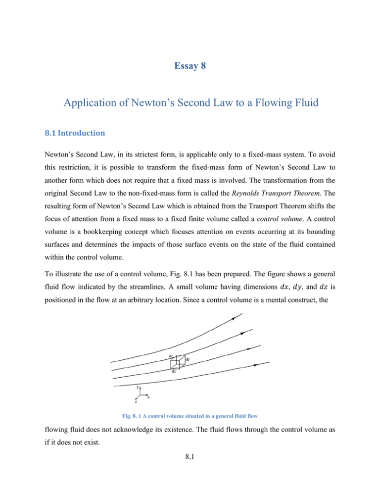
Essay 8 Application of Newton’s Second Law to a Flowing Fluid 8.1 Introduction Newton’s Second Law, in its strictest form, is applicable only to a fixed-mass system. To avoid this restriction, it is possible to transform the fixed-mass form of Newton’s Second Law to another form which does not require that a fixed mass is involved. The transformation from the original Second Law to the non-fixed-mass form is called the Reynolds Transport Theorem. The resulting form of Newton’s Second Law which is obtained from the Transport Theorem shifts the focus of attention from a fixed mass to a fixed finite volume called a control volume. A control volume is a bookkeeping concept which focuses attention on events occurring at its bounding surfaces and determines the impacts of those surface events on the state of the fluid contained within the control volume. To illustrate the use of a control volume, Fig. 8.1 has been prepared. The figure shows a general fluid flow indicated by the streamlines. A small volume having dimensions 𝑑𝑥, 𝑑𝑦, and 𝑑𝑧 is positioned in the flow at an arbitrary location. Since a control volume is a mental construct, the Fig. 8. 1 A control volume situated in a general fluid flow flowing fluid does not acknowledge its existence. The fluid flows through the control volume as if it does not exist. 8.1 When the Reynolds Transport Theorem is employed, the original fixed-mass version of Newton’s Second Law is replaced by: For a control volume and for each coordinate direction, the net force acting on the surfaces and on the volume (body force) must equal the net rate of outflow of momentum. 8.2 Net Directional Forces Acting on a Control Volume The forces and the momentums in question are with respect to a given coordinate direction. Since there are, in general, three coordinate directions, there are three individual force−momentum balance equations, one in each coordinate direction. For the derivation, attention is focused on the x-direction. The x-direction stresses on the respective faces of a small control volume having a volume 𝑑𝑥 𝑑𝑦 𝑑𝑧 are illustrated in Fig 8.2. The first subscript in the notation 𝜏𝑖𝑗 in the name of the face on which the stress acts, and the second subscript is the stress direction. Fig. 8. 2 x-direction stresses on a rectangular control volume The direction of positive forces corresponds to the positive faces, and, contrariwise, the negatively directed forces are related to the negative faces. A face is defined as positive if the normal to the face coincides with the positive coordinate direction. To begin the derivation of the net x-direction forces, the stresses 𝜏𝑥𝑥 on the positive and negative x-faces are displayed in Fig. 8.3. On the positive x-face (the right-hand face), the force is 𝜏𝑥𝑥 𝑑𝑦𝑑𝑧 𝑥+𝑑𝑥 , while on the negative x-face (the left-hand face), the force is − 𝜏𝑥𝑥 𝑑𝑦𝑑𝑧 𝑥 . The net of these forces is: 𝜏𝑥𝑥 𝑥+𝑑𝑥 − 𝜏𝑥𝑥 𝑥𝑥 𝑑𝑦𝑑𝑧 (8.1) 8.2 Positive x face Negative x face Fig. 8. 3 Head-on view of the control volume highlighting the normal stresses 𝝉𝒙𝒙 It is convenient to multiply this expression by the ratio 𝑑𝑥/𝑑𝑥 . Also, from the fundamentals of differential calculus: 𝜏 𝑥𝑥 𝑥 +𝑑𝑥 − 𝜏 𝑥𝑥 𝑥 𝑑𝑥 = 𝜕𝜏 𝑥𝑥 (8.2) 𝜕𝑥 By the combination of Eqs. (8.1 and 2), the net of the normal forces on the x-faces is obtained as: 𝜕𝜏 𝑥𝑥 𝜕𝑥 𝑑𝑥𝑑𝑦𝑑𝑧 (8.3) Next, the x-directed shear forces on the y-faces will be examined. These forces can also be conveniently viewed in a head-on view of the control volume as illustrated in Fig. 8.4. The net of Positive y face Negative y face Fig. 8. 4 Head-on view of the control volume highlighting the shear stresses 𝝉𝒚𝒙 these shear forces can be obtained by the same differencing operation that was used in obtaining the net normal force. The end result of this procedure yields: 𝜕𝜏 𝑦𝑥 𝜕𝑦 𝑑𝑥𝑑𝑦𝑑𝑧 (8.4) There remains another contribution to the net x-direction force and that comes from the stresses 𝜏𝑧𝑥 . When positive and negative contributions from 𝜏𝑧𝑥 . are brought together, their net is: 𝜕𝜏 𝑧𝑥 𝜕𝑧 𝑑𝑥𝑑𝑦𝑑𝑧 (8.5) 8.3 Aside from the forces that act on the surfaces of the control volume, there is a body force which acts on the volume as a whole. If 𝑦 is as shown in Fig. 8.2, the body force is directed in the negative y-direction and need not be considered when the x-component of Newton’s Second Law is being formulated. When the three contributions to the net x-direction force are brought together from Eqs. (8.3-5), there results: 𝜕𝜏 𝑥𝑥 𝜕𝑥 + 𝜕𝜏 𝑦𝑥 𝜕𝑦 + 𝜕𝜏 𝑧𝑥 𝜕𝑧 𝑑𝑥𝑑𝑦𝑑𝑧 (8.6) This equation represents the force portion of Newton’s Second Law. 8.3 Momentum Flow Rates Into and Out Of the Control Volume The selection of the x direction for the application of Newton’s Second Law to the control volume pictured in Fig. 8.1 requires that the momentum flow rates in that direction be quantified. The momentum in a given direction is 𝑚𝑢𝑖 , where 𝑚 is the mass, and 𝑢𝑖 is a velocity component (𝑖 = 𝑥, 𝑦, and 𝑧). Correspondingly, the rate of momentum flow is 𝑚𝑢𝑖 . To facilitate the determination of the net rate of outflow of x-momentum, as required by Newton’s Second Law for a control volume, it is useful to focus attention on representative diagrams. The first diagram, Fig. 8.5, shows the left-hand face of the control volume along with dimensional nomenclature. Fig. 8. 5 Left-hand face of the control volume pictured in Fig. 8.1 The diagram shows a streamline that passes through the face. The x-component of the velocity of the streamline crossing the face is denoted by 𝑢. The mass flow rate 𝑑𝑚 that passes through the face is equal to 𝜌𝑢𝑑𝐴, where 𝑑𝐴 = 𝑑𝑦 ∙ 𝑑𝑧. Since the area 𝑑𝐴 is of differential size, so is the mass flow rate, and this is the reason that the notation 𝑑𝑚 has been employed rather than 𝑚. Let 8.4 the rate of momentum flow in the x direction be denoted by 𝑀𝑥 . Momentum flow rate is the product of mass flow rate and the velocity component corresponding to the direction of the momentum flow. Therefore, the rate at which x-momentum crosses the left-hand face is: 𝑑𝑀𝑥 = 𝑢𝑑𝑚 = 𝜌𝑢2 𝑑𝑦𝑑𝑧 (8.7) Next, attention is focused on the rate of x-momentum that passes through the top of the control volume, and Fig. 8.6 has been prepared to aid in the analysis. It can be seen from the figure that the streamline that crosses the face has all three components of the velocity. The components of special interest here are the perpendicular component 𝑣 and the x-component 𝑢. The 𝑣component carries mass across the face at the rate 𝑑𝑚 = 𝜌𝑣𝑑𝑥𝑑𝑧. To quantify the x-momentum Fig. 8. 6 Top face of the control volume pictured in Fig. 8.1 𝑑𝑀𝑥 that is transported across this face, the product of 𝑑𝑚 and 𝑢 is appropriate, so that, 𝑑𝑀𝑥 = 𝑢𝑑𝑚 = 𝜌𝑢𝑣𝑑𝑥𝑑𝑧 (8.8) This approach is followed to quantify all of the x-momentum flow rates at the six faces of the control volume. The outcome of these steps leads to: Table 8. 1 Rates of x-momentum inflow and outflow inflow 𝜌𝑢2 𝑑𝑦𝑑𝑧 𝑥 𝜌𝑢𝑣𝑑𝑥𝑑𝑧 𝑦 𝜌𝑢𝑤𝑑𝑥𝑑𝑦 𝑧 right/left bottom/top back/front outflow 𝜌𝑢 𝑑𝑦𝑑𝑧 𝑥+𝑑𝑥 𝜌𝑢𝑣𝑑𝑥𝑑𝑧 𝑦+𝑑𝑦 𝜌𝑢𝑤𝑑𝑥𝑑𝑦 𝑧+𝑑𝑧 2 From this tabulation, the net rate of x-momentum outflow is: 𝑑𝑀𝑥 net outflow = 𝑑𝑦𝑑𝑧 𝜌𝑢2 𝑥+𝑑𝑥 − 𝜌𝑢2 𝑥 +𝑑𝑥𝑑𝑧 𝜌𝑢𝑣 𝑦+𝑑𝑦 − 𝜌𝑢𝑣 +𝑑𝑥𝑑𝑦 𝜌𝑢𝑤 𝑧+𝑑𝑧 − 𝜌𝑢𝑤 𝑦 𝑧 8.5 (8.9) To simplify this equation, use may be made of a fundamental principle of differential calculus. That principle states: 𝜕𝑓 𝜕𝑥 = lim𝑑𝑥 →0 𝑓 𝑥+𝑑𝑥 −𝑓(𝑥) (8.10) 𝑑𝑥 When this definition is separately applied to each term of Eq. (8.9), there follows, 𝑑𝑀𝑥 net outflow = 𝑑𝑥𝑑𝑦𝑑𝑧 𝜕 𝜕𝑥 𝜕 𝜕 𝜌𝑢2 + 𝜕𝑦 𝜌𝑢𝑣 + 𝜕𝑧 𝜌𝑢𝑤 (8.11) Equation (8.11) is the final expression for the net rate of outflow of x-momentum. The feature of this equation that is of special note is that it is non-linear. A non-linear term is one in which the unknown appears to a power different from one. Any non-linear equation does not have a unique solution. To support this comment, consider the well-known quadratic equation, 𝑎𝑥 2 + 𝑏𝑥 + 𝑐 = 0 (8.12) There are two solutions of this equation, and it is necessary to decide which of the solutions is appropriate. By the same token, non-linear differential equations may also have more than one solution, and more often than not, physical intuition is needed to decide which is the correct solution of the problem. 8.4 The Navier-Stokes Equations By bringing together the net x-direction force from Eq. (8.6) and the net rate of x-momentum outflow from Eq. (8.11), there is obtained: 𝜕 𝜕𝑥 𝜕 𝜕 𝜌𝑢2 + 𝜕𝑦 𝜌𝑢𝑣 + 𝜕𝑧 𝜌𝑢𝑤 = 𝜕𝜏 𝑥𝑥 𝜕𝑥 + 𝜕𝜏 𝑦𝑥 𝜕𝑦 + 𝜕𝜏 𝑧𝑥 𝜕𝑧 (8.13) This equation is often referred to as the Cauchy Momentum Equation. As written, Eq. (8.13) is not complete, because the stresses are still undefined. There are a number of relationships between stress and strain that appear in the published literature. These relationships are termed constitutive relations. The constitutive equations that are used most frequently are those for a Newtonian fluid: 𝜕𝑢 2 𝜏𝑥𝑥 = −𝑝 + 2𝜇 𝜕𝑥 − 3 𝜇 𝜏𝑦𝑥 = 𝜇 𝜕𝑢 𝜏𝑧𝑥 = 𝜇 𝜕𝑢 𝜕𝑦 𝜕𝑧 𝜕𝑢 𝜕𝑥 𝜕𝑣 + 𝜕𝑦 + 𝜕𝑤 𝜕𝑧 𝜕𝑣 + 𝜕𝑥 + 𝜕𝑤 (8.14) 𝜕𝑥 8.6 The Navier-Stokes Equations, which are the most famous equations of all of fluid mechanics, are restricted to a fluid of constant density (incompressible). The incompressibility condition is expressed by: 𝜕𝑢 𝜕𝑥 𝜕𝑣 + 𝜕𝑦 + 𝜕𝑤 𝜕𝑧 =0 (8.15) As a consequence, the 𝜏𝑥𝑥 equation that is conveyed by Eq. (8.14) is truncated. The substitution of Eqs. (8.14) into the Cauchy Momentum Equation, Eq. (8.13), yields: 𝜌 𝜕 𝜕𝑥 𝜕 𝜕 𝑢2 + 𝜕𝑦 𝑢𝑣 + 𝜕𝑧 𝑢𝑤 𝜕𝑝 = − 𝜕𝑥 + 𝜇 𝜕 2𝑢 𝜕𝑥 2 𝜕2𝑢 𝜕2𝑢 + 𝜕𝑦 2 + 𝜕𝑧 2 (8.16) This is the x-component of the famous Navier-Stokes Equations. The other two components are: 𝜌 𝜌 𝜕 𝜕𝑥 𝜕 𝜕𝑥 𝜕 𝜕 𝑢𝑣 + 𝜕𝑦 𝑣 2 + 𝜕𝑧 𝑣𝑤 𝜕 𝜕 𝑢𝑤 + 𝜕𝑦 𝑣𝑤 + 𝜕𝑧 𝑤 2 𝜕𝑝 = − 𝜕𝑦 + 𝜇 𝜕𝑝 = − 𝜕𝑧 + 𝜇 𝜕2𝑣 𝜕𝑥 2 𝜕2𝑣 𝜕2𝑣 + 𝜕𝑦 2 + 𝜕𝑧 2 − 𝜌𝑔 𝜕2𝑤 𝜕𝑥 2 Note that a body force has been added to Eq. (8.17). 8.7 𝜕2𝑤 + 𝜕𝑦 2 + 𝜕2𝑤 𝜕𝑧 2 (8.17) (8.18)


