Case study #
1.3
Title
Acoustic noise troubles caused by switching noise of an elevator (lift)
Type of trouble
Acoustic noise.
Source of trouble
Elevator.
System affected
Customer's equipment.
Location
Customer premises.
Keywords
Elevator, mutual coupling, switching noise.
Version date
2004-01-01
System configuration
Acoustic noise trouble occurred at a customer premises. The customer complained that the acoustic
noise could sometimes be heard; however, it was not clear what the trouble source was. The system
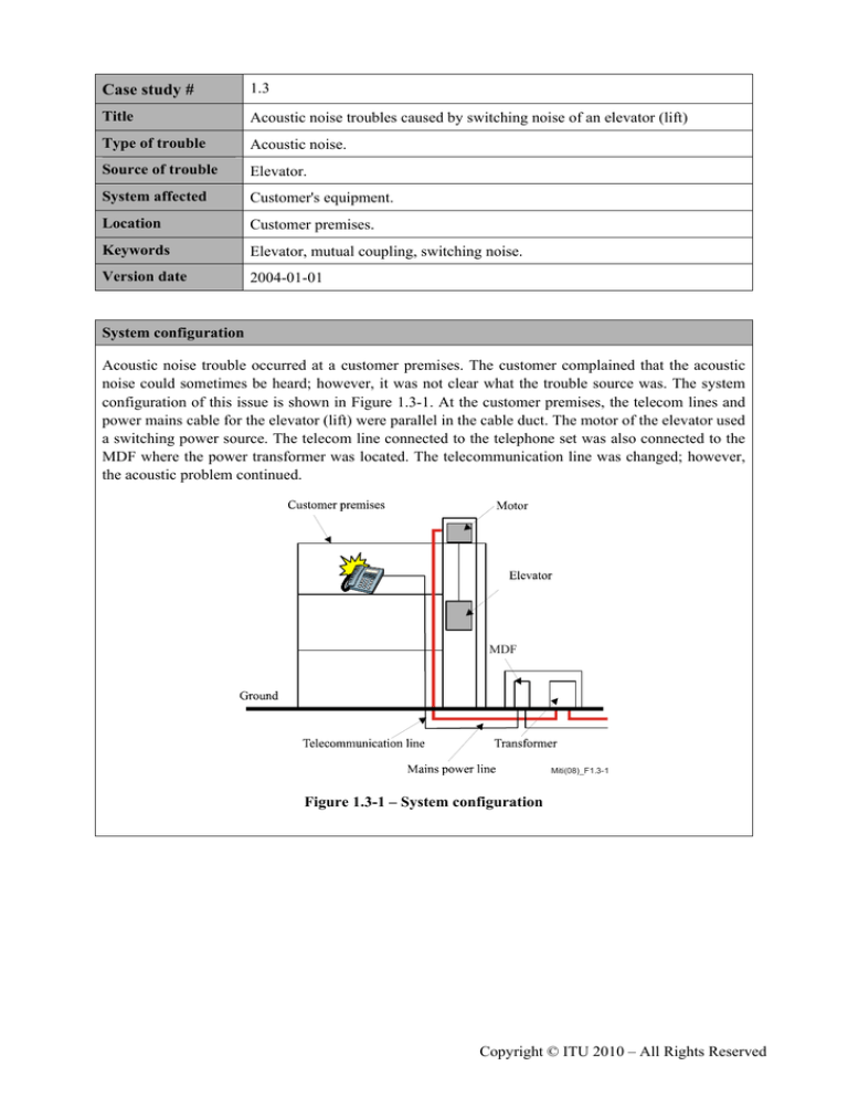
configuration of this issue is shown in Figure 1.3-1. At the customer premises, the telecom lines and
power mains cable for the elevator (lift) were parallel in the cable duct. The motor of the elevator used
a switching power source. The telecom line connected to the telephone set was also connected to the
MDF where the power transformer was located. The telecommunication line was changed; however,
the acoustic problem continued.
MDF
Miti(08)_F1.3-1
Figure 1.3-1 – System configuration
Copyright © ITU 2010 – All Rights Reserved
Measurement/Searching techniques/Experiment
To solve this acoustic problem, the current in the telecommunication line was measured
(Figure 1.3-2). The common mode current wave shape is shown in Figure 1.3-3. A typical period
200-300 μs periodic characteristic can be seen in the figure. Its major frequency is about 5 kHz and it
was estimated that the noise source must be a switching power source. The investigations showed that
the power mains cable was wired parallel to the telecommunication line, and that the
telecommunication line was connected to the main distribution frame (MDF) room, where the mains
power transformer was located.
MDF
Miti(08)_F1.3-2
Figure 1.3-2 – Measurement of noise current
5.9 V
1V
500 μs
Miti(08)_F1.3-3
Figure 1.3-3 – Current wave shape on the line connected to the telephone
Case study1.31
–2–
Mitigation method/Results/Conclusion
The acoustic problem originated in the mutual coupling of the switching noise of the motor. To solve
this problem, it was decided to apply a common mode filter to the telecommunication line and an
isolation transformer to the mains power line (see Figure 1.3-4). The isolation transformer with a filter
was attached to the mains power line, and the filter was located as near as possible to the motor, so as
to prevent the switching noise from travelling along the cable. The common mode filter at the MDF
was attached to the telecommunication line.
MDF
Miti(08)_F1.3-4
Figure 1.3-4 – Applied mitigation using common mode filter
References
Rec. ITU-T K.37; Annexes A and B.
–3–
Case study 1.3


