Datasheet
Custom WaveView ADV
Complete Transistor-Level Analysis and Debugging Environment
Overview
Custom WaveView™ ADV
provides a complete transistorlevel analysis and debugging
environment for pre-processing
and post-processing SPICE and
FastSPICE simulations. Custom
WaveView ADV is integrated with
Synopsys’ HSPICE®, FineSim® and
CustomSim™ to streamline the
debugging and analysis process for
SPICE and FastSPICE simulation
and increase design productivity.
The combination of Custom
WaveView ADV with Synopsys
circuit simulators provides design
teams with a high-performance,
productive simulation debug and
analysis environment for complex
SoC design.
Introduction
Custom WaveView ADV is a netlist-based debugging environment for SPICE
and FastSPICE simulators such as HSPICE, FineSim and CustomSim.
Custom WaveView ADV is also tightly integrated with Custom WaveView, enabling
waveform cross-probing. Together, these tools aid designers in rapidly performing
customized advanced analyses in a highly-productive design debugging and
waveform analysis environment.
Custom WaveView ADV Design Browser
The Custom WaveView ADV Design Browser allows quick access to the most
complex hierarchy design data with complete design and file display. The Design
Browser will import a netlist and allow traversing of the design hierarchy, display
signal and element list, and tracing connections contained in the hierarchy. These
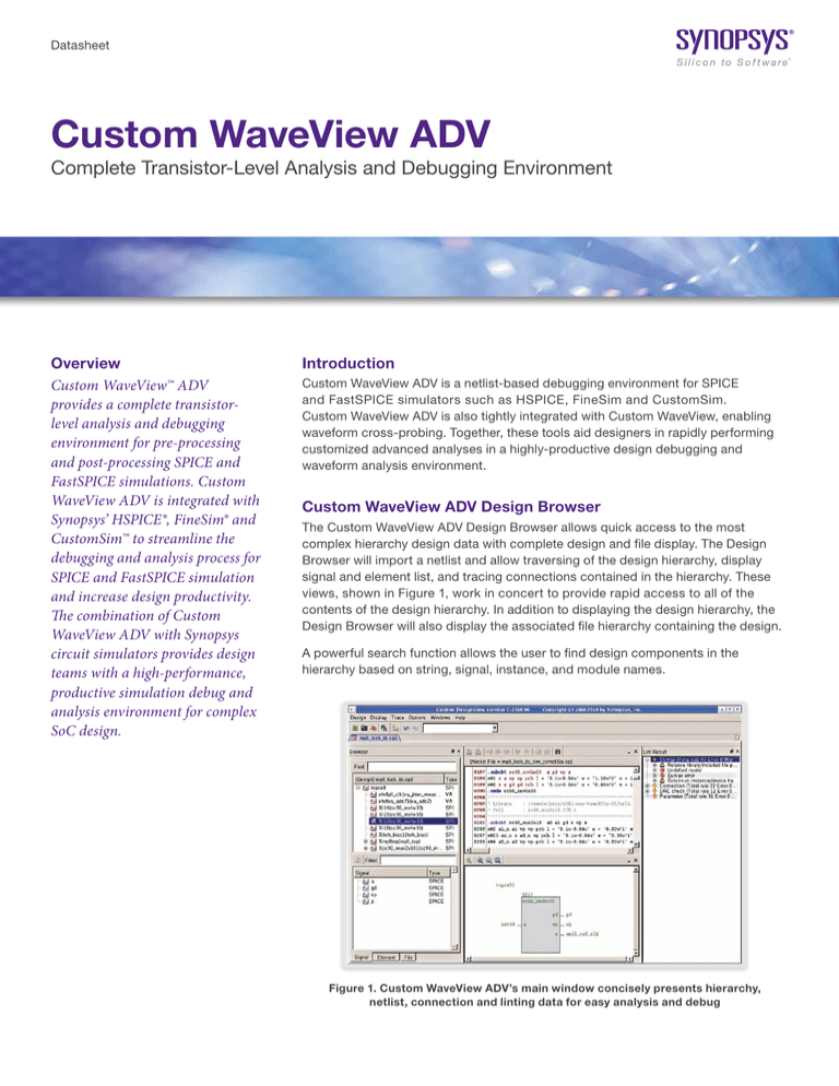
views, shown in Figure 1, work in concert to provide rapid access to all of the
contents of the design hierarchy. In addition to displaying the design hierarchy, the
Design Browser will also display the associated file hierarchy containing the design.
A powerful search function allows the user to find design components in the
hierarchy based on string, signal, instance, and module names.
Figure 1. Custom WaveView ADV’s main window concisely presents hierarchy,
netlist, connection and linting data for easy analysis and debug
Debugging
SourceView and ConnectionView
The SourceView and ConnectionView shows the contents of the SPICE netlist and creates a visualization of
the connections contained within the netlist (see Figure 1).
SourceView
The SourceView displays the hierarchical content of the SPICE netlist, allowing the designer to query the
contents of a design or cell. Selecting a subcircuit in the SourceView displays the contents of that subcircuit
as well as displaying the interface pins and netnames, and parameters in the ConnectionView.
ConnectionView
The ConnectionView creates design connectivity visualization of the object selected in the Hierarchy Browser.
Included in the diagram are the name of the object, its terminal names and the nets that connect to it. In the
case of subcircuits, the internal netnames are also displayed, making it easy to follow nets up and down
the hierarchy through subcircuit boundaries. CustomWaveView ADV’s Net Tracer can also be used to follow
changing net names with ease through the design’s hierarchy.
Signal Tracing
Signal flow can be traced in both SourceView and ConnectionView. In SourceView, the statements
representing a selected net are highlighted and can be traced subsequently. In ConnectionView, devices or
subcircuits connecting a selected signal are displayed and new connections can be displayed for pins/ports of
the connected elements.
SPICE Lint View
Custom WaveView ADV’s SPICE Lint View performs user-selected compatibility checks that can be used to
verify that the netlists being simulated conform to the proper syntax before wasting time on a long simulation
before finding a problem. These checks are performed automatically as the netlist is read in with all errors or
warnings being flagged in the SPICE Lint Window as well as the corresponding net and device being displayed
in the SourceView and ConnectionView.
SPICE Syntax Rules
Checks for basic SPICE netlist syntax and structure errors such as: missing or redundant END statements,
missing or mismatched model device names, missing ground nodes, invalid signal names, etc. Over 40
different syntax and structure checks are performed.
Connection Rules
Finds and flags problems with floating nodes or blocks, global nodes that are not driven by any source,
DC-floating MOS gate and nodes, dangling element terminals, and floating transient sources. This helps the
designer to deliver a quality netlist to the simulator of choice.
Parameter Passing and Parameter Rule Checks
Parameter passing rule checks verify that all passed parameters are properly defined before use and properly
passed through the hierarchy. Parameters that are redefined or recursively defined are also found.
The parameter rule checks also finds and flags parameter values that are set above user definable thresholds.
This includes looking for element parameter Negative capacitance/resistance, out-of-range element values
and sizes, non-positive subcircuit multiplier and PWL stimuli statements with sharp slews.
Design Connectivity Rule Checks
Looks for static DC issues such as conducting device or path, leakage device or path, as well as pulse source
errors and scale errors.
2
Custom WaveView Included
The Waveform Window is Custom WaveView (included with a Custom WaveView ADV license), the industry
standard for waveform analysis and measurement. Custom WaveView provides a host of capabilities for
displaying, measuring, manipulating and saving simulation results. In addition to multiple panels containing
waveforms, Custom WaveView also provides the ability to display more than one waveform tab allowing the
designer to mix and match time and frequency domains in a single session. Custom WaveView is a full analog
and mixed-signal display and analysis environment, reading simulation results from either analog or digital
simulators and allowing complete conversion between views. For instance, Custom WaveView can read in
the analog results of an HSPICE simulation, convert those waveforms to digital (single or multi-bit with user
selectable thresholds) and export those results for use in a digital simulation.
Full cross-probing is supported between both Custom WaveView ADV and Custom WaveView.
Other Utilities
Hierarchical Netlist Flatten and Export
Hierarchical netlists can be flattened and exported to tools that require flat netlist views. The hierarchy
information is preserved via net names in the flat netlist.
Source Waveform Preview
Stimuli statements (Pulse, PWL, Sine, Exp or SFFM) statements can be extracted from netlists and displayed
prior to simulations to verify their correctness.
Parameter Reports
A final report on all parameters in a netlist can be produced show their final values as passed to simulation.
Total Device Area Reports
The widths and lengths of transistors in netlists can be extracted and reported to help verify correct netlist
construction. This capability helps eliminate errors like missing unit values that would result in one-meter
transistors (rather than 1 micron) or 10-Farad capacitors (rather than 10 femtoFarads).
HSPICE .Measure Statement Extraction and Replay
CustomExplorer contains the ability to scan a netlist and extract out all HSPICE .Measure statements and save
them in a file. These statements retain their full design hierarchy and can be modified and replayed against
existing simulation results. This capability eliminates lost simulation time when the designer determines, after
a simulation, that additional .Measure needs to be performed, or when a given .Measure was incorrect during
the simulation. In the latter case, the simulation does not need to be rerun as the incorrect .Measure can be
fixed and replayed against the results, saving time and effort.
Batch Waveform Compare
A powerful capability in Custom WaveView ADV is the Batch Waveform Compare utility. This utility allows
designers to compare two sets of simulation runs in batch and produce a text report of the differences. The
Batch Waveform Compare system uses a simple rules file that controls the comparisons. Users can define
what signals are to be compared and the tolerances of the comparisons. Using sample-based comparison
techniques, the Batch Waveform Compare utility compares golden-to-target simulation results and supports
both analog and digital waveforms. This capability helps eliminate the vast majority of manual “eyeballing”
of analog or digital signals. Users have reported reducing as much as one full week of manual effort to 15
minutes for analyzing 100 analog waveforms.
Extensible and Open
Custom WaveView ADV is open and extensible and can be controlled in both GUI or Batch mode with
scripting. The GUI is also extensible, allowing CAD teams to craft custom measurements and provide them
across their organizations through the regular menu system.
3
Regression Scripting with the Analysis Command Environment (ACE)
The Analysis Command Environment (ACE) is a Tcl-based extension language that provides near-complete
control of Custom WaveView ADV. The ACE scripting environment contains hundreds of functions and can
control the GUI, the waveform panels, the menu system or the measurement capabilities of either tool. Often
used by CAD teams to extend the tools, the ACE scripting capability can also be used to perform Regression
Scripting allowing designers to make changes to their design and then replay a wide variety of analyses in
batch mode, freeing the designer to work on other aspects of the design. Encapsulating these analyses also
means sharing best design practices across an organization improving quality and simplifying the collection of
data for design reviews.
Industry Standard Design Platform Integrations
Custom WaveView ADV is also integrated into industry-standard design platforms to help maximize designer
productivity during the design phase. A native integration of this tool into Synopsys’ Galaxy Custom Designer ®
system helps form a complete environment for analog block authoring in a single platform for both cell-based
and custom design. Other design platform integrations include:
``
Cadence Design Systems: Virtuoso® Composer and ADE
``
JEDAT: Asca Circuit Design and Debugging Environment
``
Mentor Graphics: Design Architect® IC
``
Synopsys: Laker™ Custom Layout
``
Automation System
Supported File Formats
Custom WaveView ADV provides support for over 45 different file formats giving it the highest support of
simulation file formats in the industry.
``
Supported Simulator Formats
–– Synopsys
•
CustomSim and CustomSim FT (HSIM, XA and NanoSim — WDF, WDB, .Out and Vector)
•
HSPICE and HSPICE RF (.Tr0, .Ac0, .Sw0…— Binary and ASCII)
•
VCS (VCD and VPD)
•
Saber (AI/PL — Binary and ASCII)
–– Cadence Design Systems
•
Spectre (PSF, WSF — Binary and ASCII)
•
UltraSim (PSF, WSF — Binary and ASCII)
•
PSPICE (DAT)
•
Incisive (VCD)
–– Mentor Graphics
•
ModelSim (WLF)
•
Eldo (COU 4.3, 4.7 and Tr0)
•
ADMS (WDB and JWDB)
•
ADiT (Tr0 and Tb0)
•
HyperLynx (CSV)
–– Others
•
Agilent ADS (.ds — Binary and TouchStone S-Parameters — ASCII)
•
CSDF (ASCII)
•
Novas FSDB (Binary)
•
Legend (Tr0 Derivative)
•
SmartSPICE (Raw Derivative)
•
Five proprietary simulator formats are also available — please contact Synopsys
–– Data Formats
•
IBIS Models
•
Tektronix Agilent and Lecroy Scope Data
•
Text table data and Comma Separated Values (CSV)
4
``
Supported Netlist Formats
–– Synopsys HSPICE
–– DSPF
–– Cadence Spectre and CDL
–– Mentor Graphics Eldo
–– Standard SPICE
Platform Support
``
Microsoft Windows 64-bit
``
Red Hat Enterprise
``
SUSE Linux Enterprise (64)
Synopsys, Inc. • 690 East Middlefield Road • Mountain View, CA 94043 • www.synopsys.com
©2016 Synopsys, Inc. All rights reserved. Synopsys is a trademark of Synopsys, Inc. in the United States and other countries. A list of Synopsys trademarks is
available at http://www.synopsys.com/copyright.html . All other names mentioned herein are trademarks or registered trademarks of their respective owners.
03/25/16.CE_CS7120_Custom WaveView ADV_DS.


