Polarization in Piezoceramic Materials
advertisement

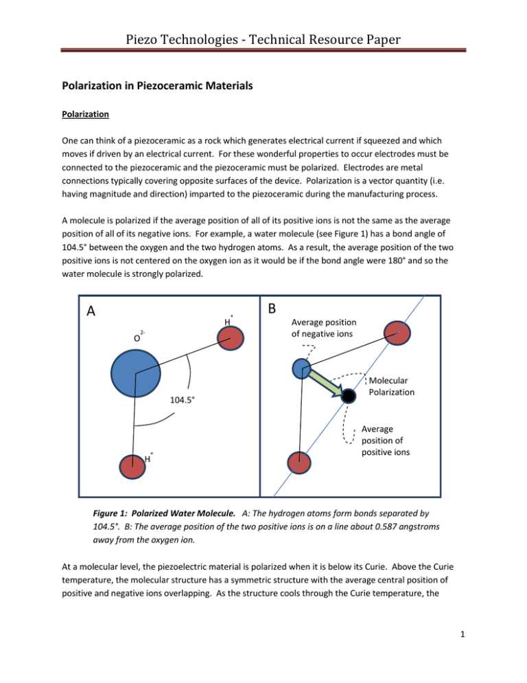
Piezo Technologies - Technical Resource Paper Polarization in Piezoceramic Materials Polarization One can think of a piezoceramic as a rock which generates electrical current if squeezed and which moves if driven by an electrical current. For these wonderful properties to occur electrodes must be connected to the piezoceramic and the piezoceramic must be polarized. Electrodes are metal connections typically covering opposite surfaces of the device. Polarization is a vector quantity (i.e. having magnitude and direction) imparted to the piezoceramic during the manufacturing process. A molecule is polarized if the average position of all of its positive ions is not the same as the average position of all of its negative ions. For example, a water molecule (see Figure 1) has a bond angle of 104.5° between the oxygen and the two hydrogen atoms. As a result, the average position of the two positive ions is not centered on the oxygen ion as it would be if the bond angle were 180° and so the water molecule is strongly polarized. A + H O 2- 104.5° + H B Average position of negative ions Molecular Polarization Average position of positive ions Figure 1: Polarized Water Molecule. A: The hydrogen atoms form bonds separated by 104.5°. B: The average position of the two positive ions is on a line about 0.587 angstroms away from the oxygen ion. At a molecular level, the piezoelectric material is polarized when it is below its Curie. Above the Curie temperature, the molecular structure has a symmetric structure with the average central position of positive and negative ions overlapping. As the structure cools through the Curie temperature, the 1 Piezo Technologies - Technical Resource Paper crystalline structure distorts and separates the average positions of the positive and negative ions (see Figure 2). A B Figure 2: Unit Cell Polarization. Polarization of a piezoelectric can be explained with the mechanical model of four balls (positive ions) located on the corners of a square frames (unit cell), which are connected by springs to a single central ball (negative ion). The bond length pushes the at-rest position of the central ion out of the plane of the four corner ions. Increasing temperature corresponds to increasing the energy of the system. A: Above the Curie temperature, the energy of the system allows the central ion to bounce from above to below the plane and the time average position is in the middle. B: If the energy of the system is too low, the central ion will be confined to stay either above or below the plane. As a result, the time average position of the ion is not in the plane and the system has a net polarization (depicted with an arrow), which points from the central negative ion to the plane of the four positive ions. The energy of this system can be described with a double well potential (see Figure 3-1). If an ion has energy greater than the small peak separating the two sides of the well (corresponding to a temperature above the Curie temperature), then the ion bounces between the steep walls at the outer limits of the well and the time averaged position is in the center. However if the energy of the ion is below the level of the small peak, then the ion will be trapped in one of the two wells of the structure. The ion will be found on one side or the other, but it is very unlikely to be found at the center. 2 Piezo Technologies - Technical Resource Paper E A E > kTC E = kTC E < kTC Polarization 0 B E E > kTC Polarization 0 E C E < kTC Polarization 0 Figure 3-1: Double well model of piezoelectric polarization. A: The energy of the central negative ion corresponds to a well with two minima. The two minima are separated by a peak in energy E = kTC, where k is the Boltzmann constant and TC is the Curie temperature. B: When the energy of the system is greater than kTC the central ion readily moves across the central peak and the time averaged probability (red dashed line) has a single peak in the middle. C: If the temperature is below the Curie temperature, then the central ion will be trapped in one of the two basins. The time average curve has two peaks, corresponding to being trapped in one or the other basin. 3 Piezo Technologies - Technical Resource Paper The energy of adjacent molecules is reduced when polarization in the two molecules are aligned. For this reason, entire domains or areas with a common direction of polarization, spontaneously arise. The size of these domains is limited both by imperfections in the material and by the field energy. Piezoceramics are not formed by a single crystal, but by grains of crystal separated by glassy interfaces and containing various flaws. The energy associated with the electric fields increases with the size of a domain, so eventually it is energetically advantageous for the field directions to flip (just like two bar magnets placed side by side will align head to tail) even in a perfect crystal. The direction of polarization of a domain can be switched by a sufficiently strong external electric field. In the spring model shown in Figure 2, this is analogous to pushing down on the central ion which was resting above the plane until it pops over to the other side and finds its other rest position below the plane. In the double well model, it is analogous to distorting the shape of the two wells (see Figure 3-2). E Polarization 0 Figure 3-2: Distorted Double Well Model of Piezoelectric Polarization. Applying an external field distorts the energy wells, and shifts the average probability of finding the central ion to the lower well. At best, the total polarization of a piezoceramic is less than about 60% of the polarization which could be found in a single crystal of the same formulation. The local domains of the ceramic are as likely to be aligned side to side as to be aligned with the axis of polarization (see Figure 4A). The force exerted by the external electrical field on the polarization is proportional to the cosine of the angle between the two vectors. This means that the force drops to zero when the domain is aligned perpendicularly to the axis, and thus, these domains are relatively unaffected by the polarization process. The result, as shown in Figure 4B, is that the polarization of only a small fraction of the domains is realigned during the polarization process. 4 Piezo Technologies - Technical Resource Paper A B External Field Net Polarization ------------------------ ++++++++++++++++++ Figure 4: Polarization. A: Prior to polarization, the material is filled with many domains with strong net polarization. However the total polarization of the sample is zero because the domains point in different directions. B: A sufficiently large external field can flip the polarization direction of some domains (red arrows). The result is a non-zero polarization, even if the external field did not change the local polarization of all of the domains. Polarization of the ceramic is not permanent. The polarized ceramic has higher energy and lower entropy than it did prior to polarization. Random variations due to heat, stress, noise and quantum tunneling will, on average, decrease the polarization of the ceramic. Depoling of ceramic is usually a logarithmic process. For example, a part may lose 2% of its net polarization in the first hour after being polarized, followed by another 2% lose in the next ten hours. Then, it will lose another 2% in the next four days, another 2% in the next year, and then another 2% in the next decade. The rate of depolarization of the piezoceramic increases rapidly as the temperature approaches the Curie temperature. 5 Piezo Technologies - Technical Resource Paper About Piezo Technologies Piezo Technologies is a world leader in providing custom-engineered Medical Ultrasonic Transducers for Air-In-Line / AIL (also referred to as Bubble Detectors or Air Sensors), as well as Diagnostic, Treatment and Therapeutic Medical Devices. We handle every aspect of our ultrasonic transducer development in-house, from piezoceramic materials formulations to fully integrated medical transducer assemblies - meeting the exact requirements of your next generation medical device. Learn more at www.PiezoTechnologies.com. 6


