Maintaining Polarity In Cassette-Based Systems
advertisement

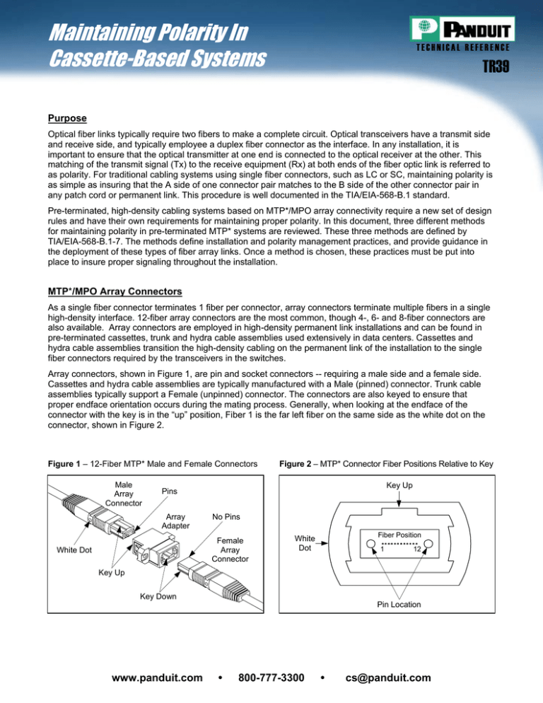
Maintaining Polarity In Cassette-Based Systems TECHNICAL REFERENCE TR39 Purpose Optical fiber links typically require two fibers to make a complete circuit. Optical transceivers have a transmit side and receive side, and typically employee a duplex fiber connector as the interface. In any installation, it is important to ensure that the optical transmitter at one end is connected to the optical receiver at the other. This matching of the transmit signal (Tx) to the receive equipment (Rx) at both ends of the fiber optic link is referred to as polarity. For traditional cabling systems using single fiber connectors, such as LC or SC, maintaining polarity is as simple as insuring that the A side of one connector pair matches to the B side of the other connector pair in any patch cord or permanent link. This procedure is well documented in the TIA/EIA-568-B.1 standard. Pre-terminated, high-density cabling systems based on MTP*/MPO array connectivity require a new set of design rules and have their own requirements for maintaining proper polarity. In this document, three different methods for maintaining polarity in pre-terminated MTP* systems are reviewed. These three methods are defined by TIA/EIA-568-B.1-7. The methods define installation and polarity management practices, and provide guidance in the deployment of these types of fiber array links. Once a method is chosen, these practices must be put into place to insure proper signaling throughout the installation. MTP*/MPO Array Connectors As a single fiber connector terminates 1 fiber per connector, array connectors terminate multiple fibers in a single high-density interface. 12-fiber array connectors are the most common, though 4-, 6- and 8-fiber connectors are also available. Array connectors are employed in high-density permanent link installations and can be found in pre-terminated cassettes, trunk and hydra cable assemblies used extensively in data centers. Cassettes and hydra cable assemblies transition the high-density cabling on the permanent link of the installation to the single fiber connectors required by the transceivers in the switches. Array connectors, shown in Figure 1, are pin and socket connectors -- requiring a male side and a female side. Cassettes and hydra cable assemblies are typically manufactured with a Male (pinned) connector. Trunk cable assemblies typically support a Female (unpinned) connector. The connectors are also keyed to ensure that proper endface orientation occurs during the mating process. Generally, when looking at the endface of the connector with the key is in the “up” position, Fiber 1 is the far left fiber on the same side as the white dot on the connector, shown in Figure 2. Figure 1 – 12-Fiber MTP* Male and Female Connectors Male Array Connector Figure 2 – MTP* Connector Fiber Positions Relative to Key Key Up Pins Array Adapter No Pins Female Array Connector White Dot Fiber Position White Dot 1 12 Key Up Key Down Pin Location www.panduit.com y 800-777-3300 y cs@panduit.com Maintaining Polarity In Cassette-Based Systems TECHNICAL REFERENCE TR39 Polarity Methods Three permanent link installation methods for deploying array or MTP*/MPO connectors are described in TIA/EIA568-B.1-7. Method ‘A’ Method ‘A’ employs Key Up to Key Down Adapters to connect the array connectors. This method, shown below, maintains registration of Fiber 1 throughout the optical circuit. Fiber 1 in the near end cassette mates to Fiber 1 in the trunk cable assembly, which mates to Fiber 1 in the remote cassette. The fiber circuit is completed by utilizing one flipped patch cord, either at the beginning or end of the permanent link, to insure proper transceiver orientation. PANDUIT recommends this method, and that the end user introduces the cable flip consistently at the beginning or end of the circuit for easier circuit management. Method ‘A’ provides the simplest deployment, works for Singlemode and Multimode channels, and easily supports network extensions. A B B A 1 1 12 12 Key Up/Key Down Adapters A B B A www.panduit.com y 800-777-3300 y 1 1 12 12 cs@panduit.com Maintaining Polarity In Cassette-Based Systems TECHNICAL REFERENCE TR39 Method ‘B’ Method ‘B’ uses Key Up to Key Up Adapters, shown below. The fiber circuit is completed by utilizing straight patch cords at the beginning and end of the link, and all of the array connectors are mated Key Up to Key Up. This type of array mating results in an inversion, meaning that Fiber one is mated with Fiber twelve, fiber two is mated with Fiber eleven, etc… To ensure proper transceiver operation with this configuration, one of the cassettes needs to be physically inverted internally so Fiber twelve is mated with Fiber one at the end of the link. This particular method requires a more in-depth planning stage in order to properly manage the polarity of the links, and to identify where the actual inversions need to occur. It also requires two separate cassettes or special labeling and management of the cassettes on one end are flipped. Further, the Key Up to Key Up method does not support Singlemode with standards compliant connector endfaces. A B B A 1 12 12 1 Key Up/Key Up Adapters B A A B www.panduit.com y 800-777-3300 y 12 1 1 12 cs@panduit.com Maintaining Polarity In Cassette-Based Systems TECHNICAL REFERENCE TR39 Method ‘C’ Method ‘C’ uses Key Up to Key Down Adapters, shown below. The fiber circuit is completed by utilizing straight patch cords at the beginning and end of the link, and the same cassettes as in Method ‘A’. The difference between this method and Method ‘A’ is that the flip does not happen in the end patch cords but in the array cable itself. This particular method requires a more in-depth planning stage in order to properly manage the polarity of the links, and to identify where the actual flipped array cord is placed in the link. An additional drawback to this method is that if this link was to be extended, a straight array cord as used in Method ‘A’ would need to be used to revert the polarity back to a straight array polarity condition; in other words, “unflip” the array cable. A B B A 1 1 12 12 Key Up/Key Down Adapters A B B A 1 1 12 12 Conclusion As illustrated and discussed above, there are three different methods recommended by TIA/EIA-568-B.1-7 to maintain polarity within array type fiber links. PANDUIT recommends Method ‘A’ due to its utilization of the onefor-one configuration throughout the link, and for its simple cable manageability. PANDUIT also realizes the compatibility of this option with possible future fiber opportunities in parallel optics (TIA/EIA-568-B.1-7 recognizes Methods ‘A” and ‘B’ as methods compatible with parallel optics) so that major reconfiguration of networks will not be necessary if this technology were to become a requirement of the end user. www.panduit.com y 800-777-3300 y cs@panduit.com


