3.12 workpiece chucking
advertisement
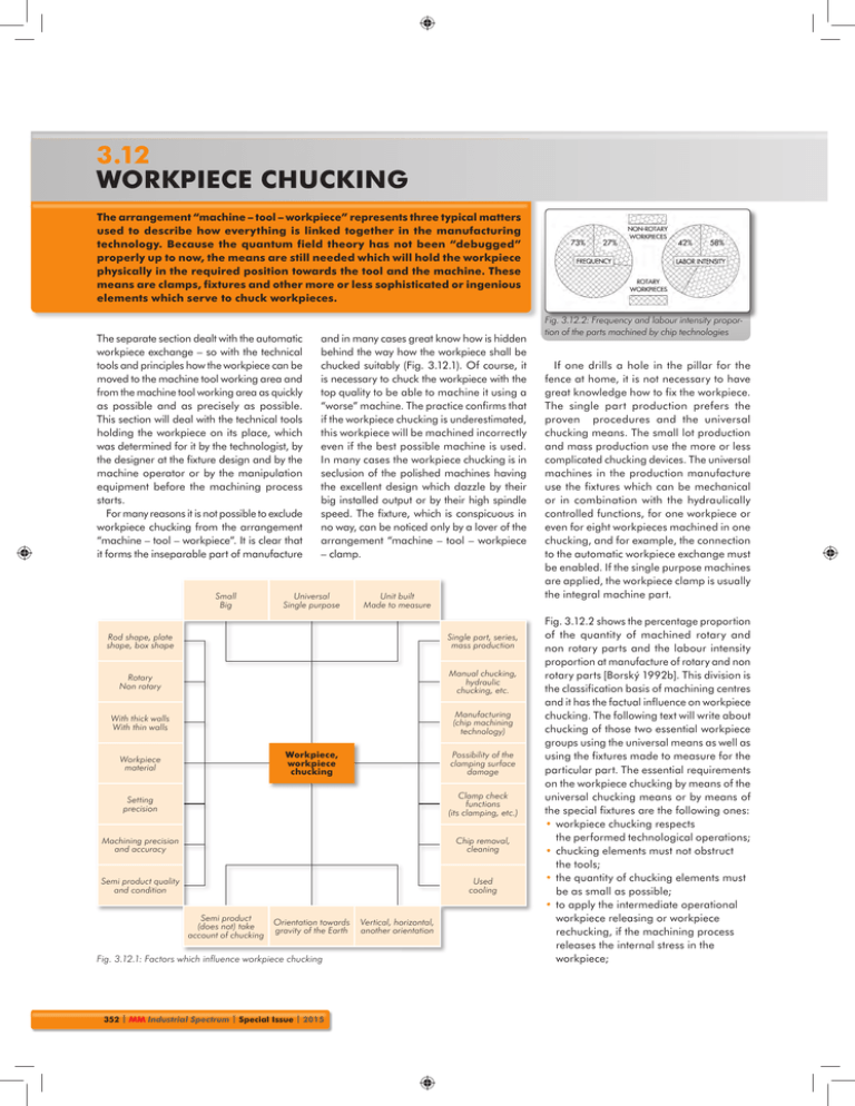
3.12 WORKPIECE CHUCKING The arrangement “machine – tool – workpiece” represents three typical matters used to describe how everything is linked together in the manufacturing technology. Because the quantum field theory has not been “debugged” properly up to now, the means are still needed which will hold the workpiece physically in the required position towards the tool and the machine. These means are clamps, fixtures and other more or less sophisticated or ingenious elements which serve to chuck workpieces. The separate section dealt with the automatic workpiece exchange – so with the technical tools and principles how the workpiece can be moved to the machine tool working area and from the machine tool working area as quickly as possible and as precisely as possible. This section will deal with the technical tools holding the workpiece on its place, which was determined for it by the technologist, by the designer at the fixture design and by the machine operator or by the manipulation equipment before the machining process starts. For many reasons it is not possible to exclude workpiece chucking from the arrangement “machine – tool – workpiece”. It is clear that it forms the inseparable part of manufacture Small Big and in many cases great know how is hidden behind the way how the workpiece shall be chucked suitably (Fig. 3.12.1). Of course, it is necessary to chuck the workpiece with the top quality to be able to machine it using a “worse” machine. The practice confirms that if the workpiece chucking is underestimated, this workpiece will be machined incorrectly even if the best possible machine is used. In many cases the workpiece chucking is in seclusion of the polished machines having the excellent design which dazzle by their big installed output or by their high spindle speed. The fixture, which is conspicuous in no way, can be noticed only by a lover of the arrangement “machine – tool – workpiece – clamp. Universal Single purpose Unit built Made to measure Rod shape, plate shape, box shape Single part, series, mass production Rotary Non rotary Manual chucking, hydraulic chucking, etc. With thick walls With thin walls Manufacturing (chip machining technology) Workpiece, workpiece chucking Workpiece material Possibility of the clamping surface damage Setting precision Clamp check functions (its clamping, etc.) Machining precision and accuracy Chip removal, cleaning Semi product quality and condition Used cooling Semi product (does not) take account of chucking Orientation towards gravity of the Earth Fig. 3.12.1: Factors which influence workpiece chucking 352 | MM Industrial Spectrum | Special Issue | 2015 Vertical, horizontal, another orientation Fig. 3.12.2: Frequency and labour intensity proportion of the parts machined by chip technologies If one drills a hole in the pillar for the fence at home, it is not necessary to have great knowledge how to fix the workpiece. The single part production prefers the proven procedures and the universal chucking means. The small lot production and mass production use the more or less complicated chucking devices. The universal machines in the production manufacture use the fixtures which can be mechanical or in combination with the hydraulically controlled functions, for one workpiece or even for eight workpieces machined in one chucking, and for example, the connection to the automatic workpiece exchange must be enabled. If the single purpose machines are applied, the workpiece clamp is usually the integral machine part. Fig. 3.12.2 shows the percentage proportion of the quantity of machined rotary and non rotary parts and the labour intensity proportion at manufacture of rotary and non rotary parts [Borský 1992b]. This division is the classification basis of machining centres and it has the factual influence on workpiece chucking. The following text will write about chucking of those two essential workpiece groups using the universal means as well as using the fixtures made to measure for the particular part. The essential requirements on the workpiece chucking by means of the universal chucking means or by means of the special fixtures are the following ones: • workpiece chucking respects the performed technological operations; • chucking elements must not obstruct the tools; • the quantity of chucking elements must be as small as possible; • to apply the intermediate operational workpiece releasing or workpiece rechucking, if the machining process releases the internal stress in the workpiece; Workpiece chucking • workpiece chucking and workpiece releasing must be possible during the smallest possible time; • chucking and clamping surfaces and elements, stops are hardened to reach the bigger mechanical resistance; • it is possible to use the self-locking principle (the designed solution must be safe); • workpiece chucking must be rigid and precise; • chucking and contact elements must catch chips to the smallest possible extent; • cutting forces should be caught by the fixed supporting surfaces; • chucking elements must be simply operable without the necessity to use special tooling; • rotating fixtures together with the workpiece must be dynamically balanced; • chucking by means of the hydraulic etc. circuits must include check and safety elements; • workpiece chucking itself, chucking elements and fixtures must be safe (safety of work). The workpiece chucking technology used at the machine is based on the requirements on its machining, i. e. how precise this machining shall be, what surface quality shall be reached, how quickly this machining shall be made, etc. The design and implementation of the workpiece chucking by means of the universal setting and chucking elements is the following one: • the design of the workpiece setting towards the machine (height over the chucking table, necessary work rests, layout of the setting elements on the machine, etc.); • the calculation of the essential chucking parameters (necessary forces, tightening moments, etc.); Fig. 3.12.3: Calculation of the fixture using the final element method [Toshulin] Fig. 3.12.4: Collet chucking on the outside workpiece surface KZZT-A [Röhm] Fig. 3.12.5: Collet chucking in the hole in the workpiece ABSIS [Röhm] Fig. 3.12.6: Workpiece chucking by means of special Belleville springs [Ringspann] • the solution design how to connect the workpiece with the machine (selection of the clamps, tightening screws, their layout, etc.); • the technical description, technical documentation, working directions (this depends on the company’s convention, internal processes, how complicated the designed solution is, whether it is necessary to buy some parts, etc.). The design as well as the implementation of the made to measure clamp (fixture) are very similar (Fig. 3.12.1). The design solution of such a clamp must take into account the connection of the workpiece and the clamp as well as the connection of the clamp and the machine. The more complicated the implementation of the made to measure clamp is, the more complex shape the part has and the bigger share of automation and mechanisation is included in the clamp. The machining forces arising during the machining process, the acceleration forces and the gravitational forces must be caught reliably by the clamp. The calculations specified to determine the chucking and reaction forces can be implemented analytically in both cases using all advantages offered by the analytical methods (velocity, clearness, etc.). The final element method also got to the design of chucking elements and this final element method helps with the check of the fixtures having the complicated shapes (Fig. 3.12.3). Chucking of rotary workpieces The basic devices serving to chuck the rotary workpieces and the workpieces which the turning operations shall be made on are the following ones: • face plates; • collet clamps for outside and inside chucking (Fig. 3.12.4 up to Fig. 3.12.6); 2015 | Special Issue | MM Industrial Spectrum | 353 3.12 WORKPIECE CHUCKING Fig. 3.12.7: Self centring chuck with the spiral mechanism [TOS Svitavy] Fig. 3.12.8: Chuck with the lever mechanism and balancing of centrifugal forces [Forkardt] • tables with the vices on their surfaces or with the built in vices; • jaw chucks: – with the spiral mechanism (Fig. 3.12.7); – with the wedge mechanism; – with the lever mechanism and balancing (Fig. 3.12.8); • other and special devices (Fig. 3.12.10 and Fig. 3.12.11). Fig. 3.12.9: Chucking force dependence on the speed of the chuck with balancing [SMW Autoblok] Fig. 3.12.10: Segment jaw chuck [Röhm] Fig. 3.12.11: Jaw chuck operated by pressure air [Röhm] Fig. 3.12.12: Self centring chuck of the type 2+2 for non rotary workpieces [HWR Spanntechnik] 354 | MM Industrial Spectrum | Special Issue | 2015 In their design and manufacturing aspects, the face plates and the tables with the vices are the simplest chucking means suitable for the single part production. The collet chucking function can be seen in the enclosed figures. Another alternative is workpiece chucking by means of the special Belleville springs. A considerable radial force is induced by their rather small pressing. Chucks are the most often used universal tool for chucking of rotary workpieces. They are primarily determined for horizontal and vertical lathe type machines. Many companies manufacturing the lathe type centres are able to design and to manufacture the chuck by themselves. The companies specialized to lathe type chucks, collets, etc. offer the chucks in the standard type as well as the highly developed technical solutions for specific branches (manufacture of bearings, railway wheels...). Their production program includes the chucks with diameters ranging from tens of centimetres up to a few meters. The self centring chucks equipped with the spiral mechanism are standardized according to the DIN 6350 and DIN 6351 standards. Fig. 3.12.7 shows the disk with the spiral
