external manhole chimney seal
advertisement

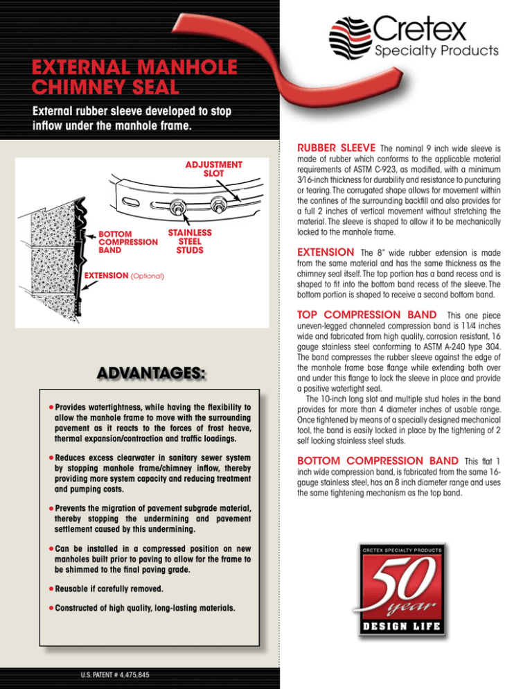
EXTERNAL MANHOLE CHIMNEY SEAL External rubber sleeve developed to stop inflow under the manhole frame. RUBBER SLEEVE The nominal 9 inch wide sleeve is ADJUSTMENT SLOT BOTTOM COMPRESSION BAND STAINLESS STEEL STUDS EXTENSION (Optional) made of rubber which conforms to the applicable material requirements of ASTM C-923, as modified, with a minimum 3⁄16-inch thickness for durability and resistance to puncturing or tearing. The corrugated shape allows for movement within the confines of the surrounding backfill and also provides for a full 2 inches of vertical movement without stretching the material. The sleeve is shaped to allow it to be mechanically locked to the manhole frame. EXTENSION The 8” wide rubber extension is made from the same material and has the same thickness as the chimney seal itself. The top portion has a band recess and is shaped to fit into the bottom band recess of the sleeve. The bottom portion is shaped to receive a second bottom band. TOP COMPRESSION BAND ADVANTAGES: Provides watertightness, while having the flexibility to •allow the manhole frame to move with the surrounding pavement as it reacts to the forces of frost heave, thermal expansion/contraction and traffic loadings. excess clearwater in sanitary sewer system •byReduces stopping manhole frame/chimney inflow, thereby providing more system capacity and reducing treatment and pumping costs. Prevents the migration of pavement subgrade material, •thereby stopping the undermining and pavement settlement caused by this undermining. Can be installed in a compressed position on new •manholes built prior to paving to allow for the frame to be shimmed to the final paving grade. •Reusable if carefully removed. •Constructed of high quality, long-lasting materials. U.S. PATENT # 4,475,845 This one piece uneven-legged channeled compression band is 11⁄4 inches wide and fabricated from high qual­ity, corrosion resistant, 16 gauge stainless steel conforming to ASTM A-240 type 304. The band compresses the rubber sleeve against the edge of the manhole frame base flange while extending both over and under this flange to lock the sleeve in place and provide a positive watertight seal. The 10-inch long slot and multiple stud holes in the band provides for more than 4 diameter inches of usable range. Once tightened by means of a specially designed mechanical tool, the band is easily locked in place by the tightening of 2 self locking stainless steel studs. BOTTOM COMPRESSION BAND This flat 1 inch wide compression band, is fabricated from the same 16gauge stainless steel, has an 8 inch diameter range and uses the same tightening mechanism as the top band. SPECIFICATIONS GENERAL This section includes the materials and procedures required for the external sealing of the entire chimney area of all sanitary manholes. FRAME SEAL Frame seals shall be designed to prevent leakage of water through the above described portions of the manhole throughout a 50 year design life.The seal shall remain flexible throughout this design life, allowing repeated vertical movements of the frame of not less than 2 inches and/or repeated horizontal movement of not less than 1/2 inch, at rates greater than 1/10 inch per minute. Frame seals shall consist of a flexible external rubber sleeve, extension, and stainless steel compression bands, all conforming to the following requirements: 1. RUBBER SLEEVE AND EXTENSION - The flexible rubber sleeve and extension shall be extruded or molded from a high grade rubber compound conforming to the applicable material requirements of ASTM C-923, with a minimum 1500 psi tensile strength, maximum 18% compression set and a hardness (durometer) of 48+5. The sleeve shall be corrugated, with a minimum thickness of 3/16 inches and shall be available in unexpanded vertical heights of 6 and 9 inches. The top section of the sleeve shall contain multiple sealing fins and be designed to extend both over and under the manhole frame’s base flange, thereby allowing it to be mechanically locked to the frame. The bottom section of the sleeve shall contain an integrally formed compression band recess and multiple sealing fins. The extension shall have a minimum thickness of 3/16 inches. The top portion of the extension shall be shaped to fit into the bottom band recess of the sleeve and have its own integrally formed band recess, which is located such that when assembled this recess is centered over that of the sleeve. The bottom section of the extension shall contain an integrally formed compression band recess and multiple sealing fins. Any splice used to fabricate the sleeve and extension shall be hot vulcanized and have a strength such that the sleeve shall withstand a 180 degree bend with no visible separation. 2. COMPRESSION BANDS - The compression bands used to compress the sleeve against the manhole shall be 16 gauge stainless steel conforming to ASTM A-240, Type 304, with a minimum width of 1 inch. The top compression band shall have a shape and width sufficient to, when tightened, mechanically lock the sleeve to the manhole frame’s base flange. The tightening mechanism on both bands shall have the capacity to develop the pressures necessary to make a watertight seal and shall have a minimum adjustment range of 4 diameter inches. Screws, bolts and nuts used on the bands shall be stainless steel conforming to ASTM F-593 and 594, Type 304. INSTALLATION The contractor shall field measure the manhole to determine the information required on the manufacturer’s “Sizing and Ordering” procedure. This information is needed to obtain the proper size of the bands, the size and shape of the rubber sleeve and the need for and size of any extensions. The surfaces against which the sleeve and extension are to be compressed shall be circular, clean, reasonably smooth and free of any form offsets or excessive voids. The top external portions of the cone shall have a minimum 2 inch high vertical surface. The preparation of this vertical surface when none exists shall be in accordance with the frame seal manufacturer’s instructions. Any flaws in the manhole frame such as cracks, pits of protrusions, shall be repaired by either filling with mortar or grinding smooth. The manhole frame shall be set to the required grade while sitting on the three 3/4 inch steel spacers which have been totally embedded in a course of cementitious grout mixed to a mortar consistency. After the rubber sleeve and where needed, an extension has been placed in the proper position, the stainless steel compression bands shall be installed in the proper locations and individually tightened as required to provide a watertight seal. Installation shall be in accordance with the manufacturer’s instructions. PHYSICAL PROPERTIES Tensile Strength.................1500 psi Elongation at break............350% min. Hardness (Durometer).......48+5 Accelerated oven-aging......max. 15% decrease of tensile, .20% of elongation Chemical resistance..........no weight loss in 1 N of sulfuric .or hydrochloric acid Compression set................18% max. Decrease Water absorption...............max. 10% increase by weight Ozone resistance...............rating 0 Low temperature brittle point.................No fracture at -40°C. Tear resistance..................200 lb. f/in. Splice strength..................180° bend with no visible sepa .ration. Sizing and ordering procedure MEASUREMENTS ORDERING FRAME — Measure the outside diameter and thickness of the base flange. SLEEVE AND EXTENSION DIAMETER — Order the sleeve size closest to the average of the flange diameter D2 and the chimney or cone diameter C3 or C4. Order the extension size closest to the average of the chimney diameter C3 or cone diameter C4. 1.The outside diameter of the base flange D2 can not be more than approximately 4 inches less than the outside diameter of the chimney C3 or cone/corbel C4. 2.The thickness of the base flange can not exceed 1 inch. CHIMNEY — For chimneys that are more than 6 inches high, measure the outside diameter C3 and height H1. CONE/CORBEL — for chimneys that have a height H1 of 6 inches or less, or where an extension is to be used, measure the outside diameter C4 and the height of the straight section H3 of the cone/corbel. See installation instructions if H3 is less than 2 inches. SLEEVE HEIGHT — If the height H1 or the combined height of H1 and H3 is 4-1/2 inches or more, order the standard width sleeve. If the combined height is less than this minimum, but at least 2-1/2 inches, order the special narrow sleeve. If the height H1 is greater than 6-1/2 inches, consideration should be given to using an extension. BAND DIAMETER — Order the top and bottom whose size range covers the flange diameter D2 and the chimney or cone diameter C3 or C4 respectively. SEAL SIZES The sleeves and extensions are normally available in 32, 34, 36, 38 and 40 inch diameters. The sleeve is available in both the standard 9 inch and narrow 6 inch height and the extensions in a single 8 inch height. The top bands are normally available in four sizes for 30-32, 34-36, 38-40 and 42-44 inch diameters, each with over four inches of range, and the bottom bands in two sizes for 34-40 and 38-44 inch diameters, each with over 8 inches of range. ORDERING AND REPORT FORM Community:Manhole No: Location:Date: Describe any pertinent factors: D in. 2 C in. 3 1 3 Sleeve Width: ________Standard ________Narrow Extension: ________Yes ________No H H Size Required: C in. 4 EXTERNAL installation instructions 1. Recommended New Construction Installation: Construct the manhole chimney, the outside diameter of which is within 4 inches of that of the frame base flange, to grade as required, allowing for the 3/4 inch thick joint under the frame. The sealing surface for the bottom of the sleeve and extension must be approximately 2 inches wide, reasonably smooth, vertical and circular, clean and free of any loose material or excessive voids. Non-shrink mortar must be used as needed, to prepare this surface. 2. Place a thick mortar course on top of the chimney with the three 3/4 inch thick spacers embedded in it at equal spacing. This 3/4 inch thickness is not required if the flange is 1-1/2 inches or more larger in diameter than the chimney. Do not use any butyl gasket material such as EZ Stik or Kent Seal in this joint. 3. Set the manhole frame on top of these spacers, center it on the chimney, and embed it in the mortar course. Rake the mortar free for a minimum depth of 1 inch from the outer surface and trowel smooth the joint on the inner surface. 4. Grind off or fill in any imperfections in the edge of the manhole frame base flange and remove any loose rust or scale to provide a reasonably smooth, clean sealing surface. Cut back any strengthening ribs so that they are flush with the top of and back 1/2 inch from the edge of the base flange. 5. If an extension is to be used, place it around the manhole frame and pull it over the chimney until the sealing fins bear against the vertical surface of the manhole cone. 6. Place the sleeve around the manhole frame and chimney and fit the top section of the sleeve over and under the edge of the frame base flange and lubricate the top band area of the sleeve with gasket lube. 7. Place the top compression band around the sleeve and position it with the long leg of the band extending over the top of the sleeve and the short leg extending into the slot provided in the sleeve. Install 2 studs in the appropriate set of holes, position them in the adjustment slot and draw the band tight with the special tool. Check to insure that the sleeve is sealed around its entire perimeters, check band tightness and tighten the 2 locknuts. 8. Some surfaces may have irregularities that require the use of butyl rubber caulk as a filler material to obtain a watertight seal. In such cases, lift up the bottom of the sleeve or extension, apply a bead of caulk to it’s center portion of the area of the irregularity and return it to it’s normal position. 9. If an extension is not being used, lubricate the bottom band recess area, place the bottom band around the sleeve in the recess and adjust the sleeve’s position so that the bands are approximately parallel. Install the studs and tighten the band as before. Check to insure that the sleeve is tight against the surface around its entire perimeter. Check band tightness and tighten the 2 locknuts. 10.Position the extension around the sleeve so that the top of the extension fits into the sleeve’s bottom band recess and the bands are approximately parallel. 11.Repeat step 9 to seal the top of the extension/bottom of sleeve and the bottom of the extension. 12.Backfill the area immediately around the manhole with selected material using care so as not to damage the installed seal and extension. NOTE: ALWAYS WEAR GLOVES WHEN HANDLING BANDS. Hooks on tool fit between the tool slots at the end of the band and the appropriate slot in the band Studs with 1/2" Lock Nuts TIGHTENING TOOL 15/16" Nut CRETEX SPECIALTY PRODUCTS N16 W23390 Stoneridge Dr-A , Waukesha, WI 53188 262-542-8153 • Fax 262-542-0301 • 800-345-3764 • www.cretexseals.com


