Φ21 Fall 2006 HW9 Solutions 1 OE-41
advertisement

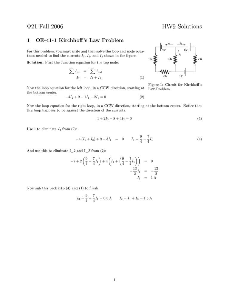
Φ21 Fall 2006 HW9 Solutions 1 OE-41-1 Kirchho's Law Problem For this problem, you must write and then solve the loop and node equations needed to nd the currents I1 , I2 , and I3 shown in the gure. Solution: First the Junction equation for the top node: ∑ Iin I2 = ∑ Iout = I1 + I3 (1) Figure 1: Circuit for Kirchho 's Now the loop equation for the left loop, in a CCW direction, starting at Law Problem the bottom center. −4I2 + 9 − 1I1 − 2I1 = 0 (2) Now the loop equation for the right loop, in a CCW direction, starting at the bottom center. Notice that this loop happens to be against the direction of the currents. 1 + 2I3 − 8 + 4I2 = 0 Use 1 to eliminate I2 (3) from (2): −4 (I1 + I3 ) + 9 − 3I1 = 0 I3 = 9 7 − I1 4 4 And use this to eliminate I_2 and I_3 from (2): ( −7 + 2 9 7 − I1 4 4 ) ( ( )) 9 7 + 4 I1 + − I1 = 0 4 4 13 13 − I1 = − 2 2 I1 = 1 A Now sub this back into (4) and (1) to nish. I3 = 9 7 − I1 = 0.5 A 4 4 I2 = I1 + I3 = 1.5 A 1 (4) 2 K 31.76 Time Constant in RC Circuit Part A. What is ∆VC a very long time after the switch is closed? So- lution: Once the capacitor is closed, the current is zero and only the battery and the capacitor matter (∆VR Part B. What is the charge Qmax = IR = 0), ∆VC = E . so that builds up on the capacitor a Solution: The charge is very long time after the switch has closed? Qmax = CV = CE . Part C. In this circuit, does The current I I = +dQ/dt or battery. Since the capacitor starts uncharged, 0. I = −dQ/dt? Therefore, the current Q is increasing, so dQ/dt > I = dQ/dt. Figure 2: The capacitor begins to Part D. What is the correct expression for the current that τ = RC Solution: will ow clockwise out of the positive terminal of the and x exp(x) = e I at time t? (Note .) Solution: Initially, the charge on the charge after the switch closes at t=0 s. capacitor is zero, so as you go around a Kirchho loop, there is only the battery and the resistor. Thus, the I0 = E/R. t = 0), so: initial current is (which is 1 at The form of the solution is just this initial current times the decaying exponential I(t) = I0 e−t/τ = E · ( ) 1 t · exp − R τ 3 K31.78 Energy Loss in an RC Circuit (Note, the numbers in this problem are randomized.) a for a very long b for 0.2 ms, then Ω resistor? The switch in Figure 3 has been in position suddenly ipped at time t=0 to position How much energy is dissipated by the 50 time. It is back to a. Solution: The capacitor eventually charges up to the battery voltage with position a. So its initial energy is U0 = 1 1 2 CV 2 = (20 µF) (50 V) = 0.025 J 2 2 When the switch is ipped to b, nentially, with the time constant the capacitor starts discharging expo- Figure 3: τ = RC = (50 Ω) (20 µF) = 1 ms. K31.78. The current, charge, and voltage (because it's proportional to charge, i.e. V = Q/C.) Circuit for problem all follow this same ex- ponential decay. (The energy doesn't, because it's voltage squared.) After 0.2 ms, the voltage across the capacitor is decreased, so the new energy is U1 = )2 ( )2 1 1 1 ( CV 2 = C V0 e−t/RC = (20 µF) 50 V e−0.2/1.0 = 0.01676 J 2 2 2 All of the missing energy is dissipated by the resistor as heat. ER = U0 − U1 = 8.24 mJ The energy could also be calculated by integrating the power in the resistor, (notice the 2 in the exponential because it gets squared): ∫ ER = ∫ tf 2 I R=R I02 exp −2t/RC 0 2 = R (V0 /R) = −RC t [exp −2t/RC]0f 2 1 CV 2 (1 − exp −2tf /RC) = U0 − U1 2 0 2 P = IV = I 2 R as follows 4 OE 41-4 Two capacitors, change K (Note, the numbers in this problem are randomized.) Two capacitors (1 and 2) are connected in parallel as shown in panel (a) Capacitor 1 has an insulator (dielectric constant K ) that KC10 ; capacitor 2 has only air between its plates. Each capacitor acquires a charge when 0 connected to the voltage V0 . For this problem, use the values C1 = 2 µF, 0 C2 = 5 µF, K = 4 , and V0 = 6 V. of Figure 4. lls the space between the plates, and its capacitance is Parts A and B. What are the charges Q1 and Q2 on the capacitors for the setup shown in panel (a)? Solution: Capacitor 1 is modied by the dielectric, while Capacitor 2 is not, so Q1 Q2 ( ) = C1 V0 = KC10 V0 = 4 2 × 10⁻⁶ (6) = 48 µC ( ) = C2 V0 = C20 V0 = 5 × 10⁻⁶ (6) = 30 µC Parts C and D. Without discharging the capacitors, the voltage Figure 4: Problem OE 41-4. V0 is disconnected, and the dielectric is removed from the rst capacitor. Then a dielectric (also dielectric constant K = 4) is inserted to ll the space between the plates of the second capacitor. This nal setup is shown in panel (b). What is the charge now on Capacitors 1 and 2? Q01 and Q02 . Since the capacitors are separated from the 0 0 rest of the world, the total charge, Qtot = Q1 + Q2 = Q1 + Q2 = 78 µC, cannot change. The capacitors are still in parallel, so the voltages across them must be equal: Solution: Call the new charges on the capacitors V1 Q01 C1 Q01 2 × 10⁻⁶ ( ) 20 × 10−6 Q01 = V2 Q02 = C2 78 × 10−6 − Q01 = 4 (5 × 10⁻⁶ ) ( ) ( ) = 156 × 10−12 − 2 × 10⁻⁶ Q01 Q01 = 7.09 × 10⁻⁶ C Q02 = 78 × 10−6 − Q01 = 70.91 µC 3


