Autotransformer Starting of Motors
advertisement
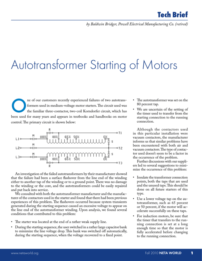
Tech Brief by Baldwin Bridger, Powell Electrical Manufacturing Co. (retired) Autotransformer Starting of Motors O ne of our customers recently experienced failures of two autotransformers used in medium-voltage motor starters. The circuit used was the familiar three-contactor, two-coil Korndorfer circuit, which has been used for many years and appears in textbooks and handbooks on motor control. The primary circuit is shown below: An investigation of the failed autotransformers by their manufacturer showed that the failure had been a surface flashover from the line end of the winding either to another tap of the winding or to a ground point. There was no damage to the winding or the core, and the autotransformers could be easily repaired and put back into service. We consulted with both the autotransformer manufacturer and the manufacturer of the contactors used in the starter and found that there had been previous experiences of this problem. The flashovers occurred because system transients generated during the starting sequence caused an excessive voltage to appear on the line end of the autotransformer winding. Upon analysis, we found several conditions that contributed to this problem: • The starter was located at the end of a rather weak supply line. • During the starting sequence, the user switched in a rather large capacitor bank to minimize the line voltage drop. This bank was switched off automatically, during the starting sequence, when the voltage recovered to a fixed point. www.netaworld.org • The autotransformer was set on the 80 percent tap. • We are uncertain of the setting of the timer used to transfer from the starting connection to the running connection. Although the contactors used in this particular installation were vacuum contactors, the manufacturer informs us that similar problems have been encountered with both air and vacuum contactors. The type of contactor used doesn’t seem to be a factor in the occurrence of the problem. Further discussions with our suppliers led to several suggestions to minimize the occurrence of this problem: • Insulate the transformer connection points, both the taps that are used and the unused taps. This should be done on all future starters of this type. • Use a lower voltage tap on the autotransformer, such as 65 percent or 50 percent, if the motor will accelerate successfully on these taps. • For induction motors, be sure that the timer that transfers to the running connection is set at a long enough time so that the motor is fully accelerated before changing to the running connection. Fall 2010 NETA WORLD 1 • Add an instantaneous current relay to the circuit, set to pick up at about five amperes and drop out just below that current. This relay will pick up when the motor is started and drop out when it reaches full speed. Connect the coil of this relay in any phase CT. Use the contact of this relay to bypass the timing relay contact, insuring that the motor has fully accelerated before the starter is transferred to the running connection. See the control circuit below. In the future, please include this relay in all starters of this type. 2 NETA WORLD Fall 2010 • In extreme cases, it may be necessary to connect intermediate class surge arresters to the line taps of the two autotransformer coils. Baldwin Bridger is recently retired Technical Director of Powell Electrical Manufacturing Co., Houston, Texas. He has worked as an engineer and engineering manager in the design of low- and medium-voltage switchgear since 1950, first at GE and since 1973 at Powell. He is a Fellow of IEEE and a past president of the IEEE Industry Applications Society. www.netaworld.org
