Computer Science: An Overview Edition 8 Activities Chapter 1, Data
advertisement

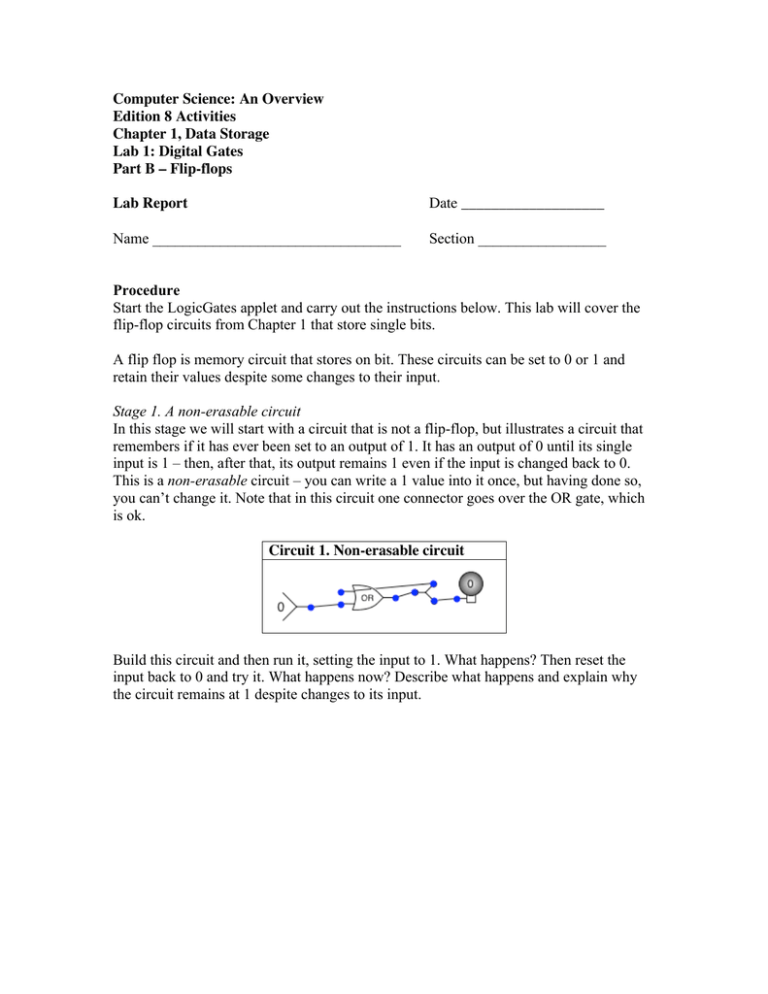
Computer Science: An Overview Edition 8 Activities Chapter 1, Data Storage Lab 1: Digital Gates Part B – Flip-flops Lab Report Date ___________________ Name _________________________________ Section _________________ Procedure Start the LogicGates applet and carry out the instructions below. This lab will cover the flip-flop circuits from Chapter 1 that store single bits. A flip flop is memory circuit that stores on bit. These circuits can be set to 0 or 1 and retain their values despite some changes to their input. Stage 1. A non-erasable circuit In this stage we will start with a circuit that is not a flip-flop, but illustrates a circuit that remembers if it has ever been set to an output of 1. It has an output of 0 until its single input is 1 – then, after that, its output remains 1 even if the input is changed back to 0. This is a non-erasable circuit – you can write a 1 value into it once, but having done so, you can’t change it. Note that in this circuit one connector goes over the OR gate, which is ok. Circuit 1. Non-erasable circuit Build this circuit and then run it, setting the input to 1. What happens? Then reset the input back to 0 and try it. What happens now? Describe what happens and explain why the circuit remains at 1 despite changes to its input. Stage 2. An OR/AND/NOT flip-flop In this stage you will test the flip-flop circuit from Figure 1.4 on page 23. Build this circuit. Circuit 2. OR/AND/NOT flip-flop A. Set the lower input to 1 and then change the upper input back and front between 0 and 1. What happens to the output? B. First set the lower input to 1 and the upper input to 0. The output light should be 0. Now set the lower input to 0 so you should have upper as 1, lower as 0. 1. What is the value of the output? ________ 2. What happens when you switch the upper input from 0 to 1? 3. What happens when you switch the upper input back from 1 to 0? 4. What is the similarity between this flip-flop and the Non-erasable circuit in Stage 1? Stage 2. An OR/AND flip-flop In this stage you will test the flip-flop circuit from Figure 1.5 on page 24. Build the circuit below. Circuit 3. OR/NOT flip-flop Now investigate this circuit to figure out how it works. What happens when you hold the lower input to 0 and change the upper input? What happens when you hold the lower input to 1 and change the upper input? How does this flip-flop work? Does it work exactly the same as the OR/AND/NOT flipflop?


