Model 30573-0003 Mini Accumulator Tank
advertisement

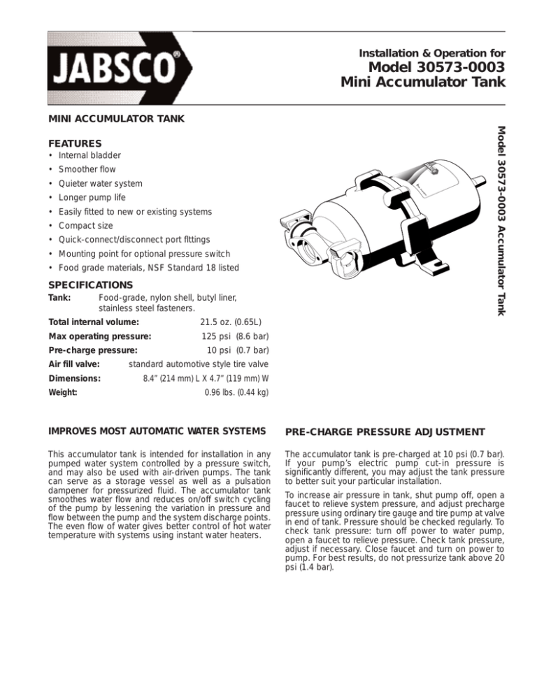
Installation & Operation for Model 30573-0003 Mini Accumulator Tank MINI ACCUMULATOR TANK Model 30573-0003 Accumulator Tank FEATURES • Internal bladder • Smoother flow • Quieter water system • Longer pump life • Easily fitted to new or existing systems • Compact size • Quick-connect/disconnect port flttings • Mounting point for optional pressure switch • Food grade materials, NSF Standard 18 listed SPECIFICATIONS Tank: Food-grade, nylon shell, butyl liner, stainless steel fasteners. Total internal volume: 21.5 oz. (0.65L) Max operating pressure: 125 psi (8.6 bar) Pre-charge pressure: 10 psi (0.7 bar) Air fill valve: standard automotive style tire valve Dimensions: 8.4” (214 mm) L X 4.7” (119 mm) W Weight: 0.96 lbs. (0.44 kg) IMPROVES MOST AUTOMATIC WATER SYSTEMS PRE-CHARGE PRESSURE ADJUSTMENT This accumulator tank is intended for installation in any pumped water system controlled by a pressure switch, and may also be used with air-driven pumps. The tank can serve as a storage vessel as well as a pulsation dampener for pressurized fluid. The accumulator tank smoothes water flow and reduces on/off switch cycling of the pump by lessening the variation in pressure and flow between the pump and the system discharge points. The even flow of water gives better control of hot water temperature with systems using instant water heaters. The accumulator tank is pre-charged at 10 psi (0.7 bar). If your pump’s electric pump cut-in pressure is significantly different, you may adjust the tank pressure to better suit your particular installation. To increase air pressure in tank, shut pump off, open a faucet to relieve system pressure, and adjust precharge pressure using ordinary tire gauge and tire pump at valve in end of tank. Pressure should be checked regularly. To check tank pressure: turn off power to water pump, open a faucet to relieve pressure. Check tank pressure, adjust if necessary. Close faucet and turn on power to pump. For best results, do not pressurize tank above 20 psi (1.4 bar). TYPICAL INSTALLATION Disconnect power supply to pump. Open the faucet or appliance discharge valve. Tank installs anywhere in-line on discharge side of pump. Fasten hose to inlet/outlet fittings securely with hose clamps. Failure to do so may result in flooding and/or equipment damage. Restore water supply, then restore power supply. Allow water to flow through pump and out final discharge point in order to eliminate air from system. Tank may be mounted in any position. To remove the tank from the system, always disconnect power source to the pump, and open a faucet or appliance to safely vent water under pressure. SAFETY If possible, use a safety relief valve set for 125 psi (8.6 bar) max., installed in-line on the pump discharge side. Use flexible braided hose to minimize noise and/or vibration. Hose should be rated for pressure levels expected of each system. REPLACEMENT PORTS 30654-1000 1/2” (13 mm) Straight Hose Barb 30649-1000 1/2” (13 mm) Threaded All parts 2 per bag HOW THE PRESSURE ACCUMULATOR WORKS Pre-Pressurized Air Cushion Bladder 10 psi 0-10 40-75 40-75 psi A. Air Valve 30 psi 30 B. C. A. Factory installed precharged air cushion. B. When pump starts, water enters the reservoir. At maximum pressure, system is filled. Pump shuts off. C. When water is demanded, pressure in the air chamber forces water into the system. Pump stays off until minimum pressure is reached, then pump starts and runs until cut-out pressure is reached. CAUTION Do not overpressurize tank. Pressures over 125 psi (8.6 bar) may rupture tank and cause personal injury. DIMENSIONAL DRAWING (Inches/mm) Barb Fitting 1/2" ID Hose 4.38 (11) 2.25 (57) 0.83 (21) 3.20 (81) 8.43 (214) 3.40 (86) 3.98 (101) 4.68 (119) RETURN PROCEDURE PRODUCT WARRANTY Prior to returning any product to Jabsco, call customer service for an authorization number. This number must be written on the outside of the shipping package. Place a note inside the package with an explanation for return as well as the authorization number. Include your name, address and phone number. Jabsco warrants this product to be free of defects in material and/or workmanship for a period of one year after purchase by the customer from Jabsco. During this one year warranty period, Jabsco will at its option, at no charge to the customer, repair or replace this product, if found defective, with a new or reconditioned product, but not to include costs of removal or installation. No product will be accepted for return without a return material authorization number. All return goods must be shipped with transportation charges prepaid. A complete copy of our warranty is available upon request. www.jabsco.com U.S.A. Flojet Cape Ann Industrial Park Gloucester, MA 01930 Tel: 978.281.0440 Fax: 978.283.2619 Copyright 2005 UNITED KINGDOM Flojet Bingley Road, Hoddesdon Hertfordshire EN11 OBU Tel: +44 (0) 1992 450145 Fax: +44 (0) 1992 467132 CANADA Fluid Products Canada 55 Royal Road Guelph, Ontario N1H 1T1 Tel: 519 821.1900 Fax: 519 821.2569 Printed in U.S.A. JAPAN NHK Jabsco Company Ltd. 3-21-10, Shin-Yokohama Kohoku-Ku, Yokohama, 222-0033 Tel: 045.475.8906 Fax: 045.477.1162 All Rights Reserved GERMANY Jabsco GmbH Oststrasse 28 22840 Norderstedt Tel: +49-40-53 53 73 -0 Fax: +49-40-53 53 73 -11 Form: 43000-1818 ITALY Jabsco Marine Italia Via Tommaseo, 6 20059 Vimercate, Milano Tel: +39 039 685 2323 Fax: +39 039 666 307 Rev. B 12/2005


