BODE PLOTS FIRST <wm Fll.,TERS (RC or I.R) 20 -40
advertisement
APPENDIX
B
BODE PLOTS
The
Bode
plot
is
impedance).
phase
angle
Bode
is
plots
closed
gain
an
is
made
The
process
the
actual
the
frequencies
Bode's
of
the
by
is
simple
filter)
and
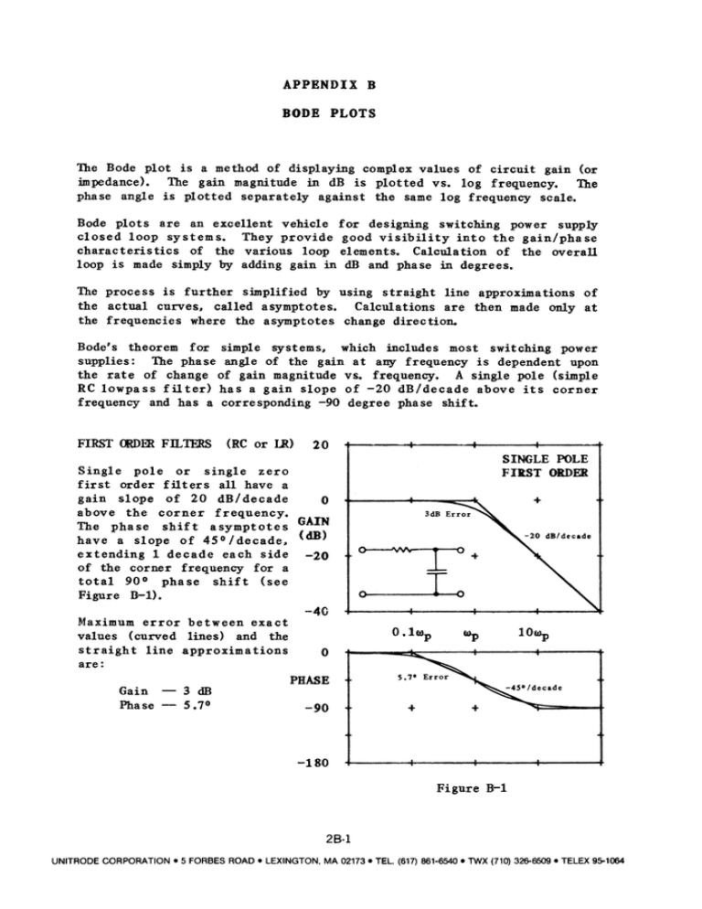
FIRST <wm
has
has
or
single
order
pole
filters
all
gain
slope
of
above
the
The
phase
of
the
slope
phase
power
the
of
supply
gain/phase
the
overall
degrees.
line
approximations
are
then
made
of
only
at
direction.
includes
most
switching
power
any frequency
is dependent
upon
frequency.
A single
pole
(simple
-20
degree
dB/decade
phase
above
its
corner
shift.
a
0
GAIN
45°/decade.
each
(dB)
side
frequency
90°
Figure
in
scale.
20
dB/decade
1 decade
of
-90
into
(or
The
zero
have
frequency.
asymptotes
of
corner
total
20
corner
shift
extending
slope
Fll.,TERS (RC or I.R)
first
a
a gain
a corresponding
phase
straight
which
frequency
Calculation
and
change
systems,
log
gain
frequency.
switching
Calculations
asymptotes
circuit
log
visibility
using
The phase
angle
of the gain
at
of change
of gain magnitude
vs.
frequency
have
by
dB
asymptotes.
the
same
elements.
in
of
vs.
designing
good
loop
values
plotted
the
for
gain
simplified
for
is
against
various
called
complex
dB
provide
adding
further
where
RC lowpass
Single
in
vehicle
They
simply
theorem
supplies:
the
rate
excellent
curves.
displaying
separately
systems.
characteristics
of
magnitude
plotted
are
loop
loop
a method
The
for
shift
-20
a
(see
8-1).
-40
Maximum
values
error
{curved
straight
line
between
lines)
exact
and
the
O.l111p
ClIp
lOIl>p
approximations
are:
Gain
-3
Phase
-5.7°
dB
Figure
8-1
28-1
UNITRODE
CORPORATION.
5 FORBES
ROAD.
LEXINGTON,
MA 02173.
TEL.
(617) 861-6540
.TWX
(710) 326-6509
.TELEX
95-1064
Low Pass -Sine:le
Pole:
Fie:ure
1
F(s)
=
B-l
IIIp
l+s/11Jp
=
l/RC
or
s = jIll
L/R,
.
-20
Gain:
~i~g1eZ~
pole
Has
shown
phase
dB/decade
in
slopes
are
F(s)
= l+s/wz,
Gain:
+20
RHP
making
it
boost
Refers
same
=
second
has
a -40
frequency
pole
+20
as
2
a
has
in
phase
eliminate
the
gain
to
provide
as
and
lead
the
the
negative,
adding
complex
like
additional
zero
in
(left-
a single
phase
above
is
continuous
s-plane.
conventional
compensation
loop
and
Figure
its
pole.
lag,
corner
encountered
inductor
by
at
wo:
Phase:
intercepts:
asymptote
-900
filter
only
current
total
in
mode.
lag
of
18>
above
degrees,
Here
varies
is
characteristic
magnitude
the
with
of
little
cause
instability.
means
Q of
same
the
as
two
single
The
resonant
unless
B-2
(resonant)
end.
frequency,
first
order
dB/decade
20
Figure
corner
the
when
gain
circuit,
resonant
it
could
degrees/decade
with
a Q of 0.5.
At
the phase
slope
becomes
much more
of
-40
the
importance
crossover
of
the
similarities
the
gain
slope
is -45
B-4
shows
Gain:
peak
LC
cascade.
This
the
compensation
Gain
Phase:
gain
which
margin
The phase
characteristic
higher
values
of Q.
F(s)
single
Gain
LC)
lag
in
B-3.
close
Phase
total
on
slope
slope
is
up while
resonant
a peak
Figure
is
making
the
8-2
slope
filters
frequency
rapid.
+900
location
gain
slope.
pole
total
order
in
its
operated
Fi2ure
order
and
shown
to
(Resonant
dB/decade
characteristic
as
frequency.
L/R
right-half-plane
dE/decade
Pole:
first
lag
l-s/IlJz
SEC<ND OODERFll,1ERS
The
with
Phase:
to
the
regulators
Gain:
Low Pass -2
or
positive
impossible
Fortunately,
F(s)
total
characteristic
increases
slope.
but
the
phase
the loop
gain
flyback
phase
gain
Wz = l/RC
virtually
and
and
-900
1>ositive.
the
zero,
zero
holds
frequency.
gain
dB/decade
has
Phase:
except
Zero.
zero
half-plane)
The RHP
same
II-l.
both
lli&h!-Half-Plane
The
the
Figure
slope.
log
-180°
w/K.
zeros
more
difficult.
slope
Q
total
Kw.
lag
1
K = S2Q
1
=
1+(s/wo)/Q+(s/wo)2
where
1
Wo = =m-".
Q =
woL/Rs.
28-2
UNITRODE CORPORATION.
5 FORBES ROAD.
LEXINGTON, MA 02173. TEL (617) 861-6540. TWX (710) 326-6509 .TELEX
95-1064
Effective
Rs
determine
capacitor
series
resistance
s Q.
Rs
ESR:
20
includes
Rc'
:
inductor:
RL'
rectifier
dynamic:
Rd,
leakage
inductance
effective
resistance:
Ri'
resistance:
into
Q
and
Ro'
seldom
5.
full
more
load.
into
loads.
(dB)
R.
-20
reaches
At
transforms
light
series
0
GAIN
transformed
its
equivalent
(L/C
= ZoZ).
or
load
high
diode
than
low
Rs.
Rd
4
Ro
-40
At
limits
Q.
0
PHASE
Figure
0
B-2
Qa
+10
-45
0=2
PHASE
0
-90
GAIN
(dB)
II\
-135
,-
-20
-180
0.2
0.4
0.8
1
2
4
0.2
~
0.4
"""'0
..1..0
Figure
2
0.81
Figure
B-4
B-3
28-3
UNITRODE
CORPORATION.
5 FORBES
ROAD.
LEXINGTON,
MA 02173.
TEL.
(617) 861-6540
.1WX
(710) 326-6509.
TELEX
95-1064
