Typical Output Amplitudes - SHF Communication Technologies AG
advertisement

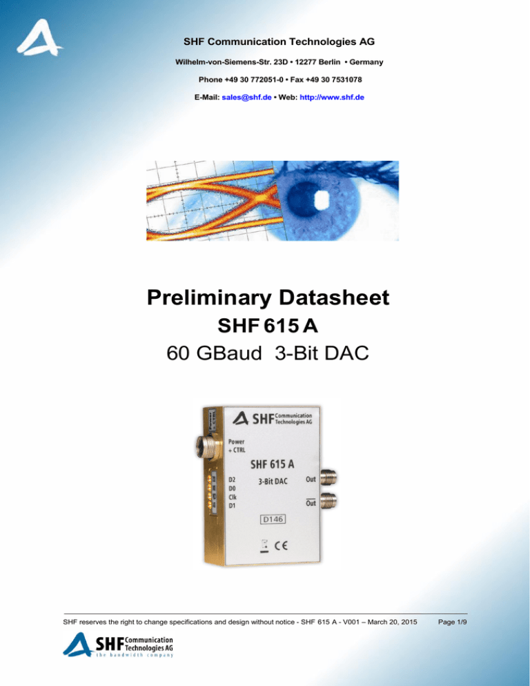
SHF Communication Technologies AG Wilhelm-von-Siemens-Str. 23D • 12277 Berlin • Germany Phone +49 30 772051-0 • Fax +49 30 7531078 E-Mail: sales@shf.de • Web: http://www.shf.de Preliminary Datasheet SHF 615 A 60 GBaud 3-Bit DAC SHF reserves the right to change specifications and design without notice - SHF 615 A - V001 – March 20, 2015 Page 1/9 Description The SHF 615 A is a 3-Bit Digital-to-Analog Converter (DAC) operating at symbol rates up to 60 GBaud for use in broadband test setups and telecom transmission systems. Up to three single ended serial data streams are accepted by the DAC and converted into one differential 8-level data signal. By using two input ports only it is possible to generate 4-level output signals. A single ended clock signal with the same frequency as the data rate drives the SHF 615 A. For data regeneration purposes all input data signals are re-sampled to mitigate any signal impairments resulting e.g. from long cables. Therefore, it becomes possible to place the DAC very close to the DUT. All RF input and output ports are AC-coupled. Features Broadband operation up to 60 GBaud Differential data output, 4.8 V differential output swing (2.4V in single-ended operation) Single-ended clock and data inputs Latched input ports Output level control Applications 100, 200, 400 Gbps and 1 Tbps system evaluation & development Broadband test and measurement equipment PAM-N, OFDM, Advanced Modulation Experiments Block Diagram Out Out SHF 615 A 3-Bit DAC Power Supply + Control D2 D0 Clk D1 (MSB) (LSB) SHF reserves the right to change specifications and design without notice - SHF 615 A - V001 – March 20, 2015 Page 2/9 Ease of Use In addition to the DAC itself, the power supply, USB cable, head sink and control software are a complementary part of each delivery. It is recommended to use the DAC only with the delivered power supply module. The easy to use software package, the SHF 600 Series Control, is the most convenient way to control the DAC. The software reads the individual calibration tables of the DAC and sets the contribution of the bias voltages accordingly. The amplitude of the individual eye openings can be set and is displayed in the graphical user interface (GUI). The enables the user to generate a perfect signal just by a few intuitive clicks. The control software for other operating systems is available on request. Fig. 2: “SHF 600 Series Control” – GUI The heat sink can be removed by the customer. In this case it is required to provide other cooling measures to ensure that the maximum case temperature specified on page 4 will not be exceeded. SHF reserves the right to change specifications and design without notice - SHF 615 A - V001 – March 20, 2015 Page 3/9 Absolute Maximum Ratings Parameter Unit Symbol Min. Typ. Max. Comment Data Input Voltage mVpp Vdata in 900 Clock Input Voltage mVpp Vclk in 900 External DC Voltage on RF Input Ports V VDCin -10 +10 AC coupled input External DC Voltage on RF Output Ports V VDCout -10 +10 AC coupled output V Vee Vcc -5.0 0 0 +6.0 Unit Symbol Min. mVampl Vdata in 300 800 GHz fin 1 60 mVampl Vclk in 300 800 Minimum Output Data Rate GBaud Rout,min Maximum Output Data Rate Gbaud Rout,max 60 62 Output Amplitude mVampl Vout 2200 2415 ps tr 8 12 10 13 20% / 80% 10% / 90% ps tf 6 9 8 11 20% / 80% 10% / 90% ps tskew ±1 ±2 Input Parameters DC Supply Voltages (DAC-Module) Specifications Parameter Typ. Max. Comment Input Parameters Data Input Voltage Clock Input Frequency Clock Input Voltage 500 mV recommended 500 mV recommended Output Parameters 1 Rise Time Fall Time 1 Differential Output Skew 1 1 Single ended, full scale, adjustable up to -6dB, see page 5 Refers to full scale output swing (measured with a 0101-pattern, phase-synchronized at all data input ports) SHF reserves the right to change specifications and design without notice - SHF 615 A - V001 – March 20, 2015 Page 4/9 Power Requirements (incl. Power Supply) Supply Voltage V Vc Supply Current mA Ic 650 Power Dissipation W Pd 7.8 +11.5 +12 +12.5 @ VC = +12V Power Requirements (DAC-Module only) Supply Voltage V Vee Supply Current mA Iee Supply Voltage V Vcc Supply Current mA Power Dissipation -4.6 -4.4 -4.3 1050 1150 +5.3 +5.5 Icc 320 350 W Pd 6.3 °C Tcase +5.2 @ VEE = -4.4V, VCC = +5.3V Conditions Case Temperature 2 10 45 Typical Output Amplitudes Below mentioned values assume no attenuation to be set in the control software. The output amplitude of the DAC can be reduced by 0 to -6 dB by making the appropriate setting in the control software. Input D2 Input D1 Input D0 Typical Output Amplitude [mV] - - On 345 - On - 690 On - - 1380 The typical output amplitude of a multilevel signal can be calculated by accumulating the typical output amplitudes of all applied input ports of the DAC as shown in the table above. Thus the full scale output swing (all inputs active) accumulates as follows: On On On 2415 2 Tr / Tf of the output data signal can be slightly decreased by applying additional cooling measures like heat sinks or cooling fans. SHF reserves the right to change specifications and design without notice - SHF 615 A - V001 – March 20, 2015 Page 5/9 Typical Output Eye Diagrams The measurements below had been performed using a SHF 12104 A Bit Pattern Generator (PRBS 31 2 -1) and a Tektronix DSA 8300 Digital Serial Analyzer (DSA) with Phase Reference Module (82A04B-60G) and 70 GHz Sampling Module (80E11). The outputs of the DAC module had been connected directly to the DSA input with a 20 dB attenuator. 4-Level Output Signal Measurement Out @ 62 GBaud Out @ 60 GBaud Out @ 56 GBaud Out @ 50 GBaud Out @ 32 GBaud Out @ 10 GBaud SHF reserves the right to change specifications and design without notice - SHF 615 A - V001 – March 20, 2015 Page 6/9 8-Level Output Signal Measurement Out @ 62 GBaud Out @ 60 GBaud Out @ 56 GBaud Out @ 50 GBaud Out @ 32 GBaud Out @ 10 GBaud SHF reserves the right to change specifications and design without notice - SHF 615 A - V001 – March 20, 2015 Page 7/9 Outline Drawing - Module 35.6 4x M2.5x5mm 6 12.4 6.3 6.4 21 12.5 60.6 29.6 3x 3.6 40.2 D1 MiniSMP (GPPO) Male D2 MiniSMP (GPPO) Male Clk MiniSMP (GPPO) Male All dimensions in mm. Out D146 Out 3-Bit DAC MiniSMP (GPPO) Male SHF 615 A 1.85mm (V) female D0 D2 D0 Clk D1 Out Power + CTRL 1.85mm (V) female Communication Technologies AG Connector Out SHF Port 40.2 40 30 16.3 65 SHF reserves the right to change specifications and design without notice - SHF 615 A - V001 – March 20, 2015 Page 8/9 Outline Drawing – Module with Heat Sink Out Out Power Supply & Control (I2C-Bus) 4 5 3 6 1 2 Power Supply & Control (I2C-Bus) SHF Out Out Communication Technologies AG 3-Bit DAC D146 SHF 615 A Power + CTRL D2 D0 Clk D1 Port Connector Pin Colour Out 1.85mm (V) female 1 brown Out 1.85mm (V) female 2 white Vcc GND D0 MiniSMP (GPPO) Male 3 blue Designation SCL D1 MiniSMP (GPPO) Male 4 black Vee D2 MiniSMP (GPPO) Male 5 grey SDA Clk MiniSMP (GPPO) Male 6 pink GND All dimensions in mm. 88.5 25 35 24.6 3x3.6 48.7 14.7 D1 Clk D0 D2 14.6 8.5 SHF Power + CTRL Communication Technologies AG SHF 615 A D146 3-Bit DAC 12.4 6 40.2 65 SHF reserves the right to change specifications and design without notice - SHF 615 A - V001 – March 20, 2015 Page 9/9


