26 29 13 - Motor Control - University of Illinois Facilities and Services
advertisement

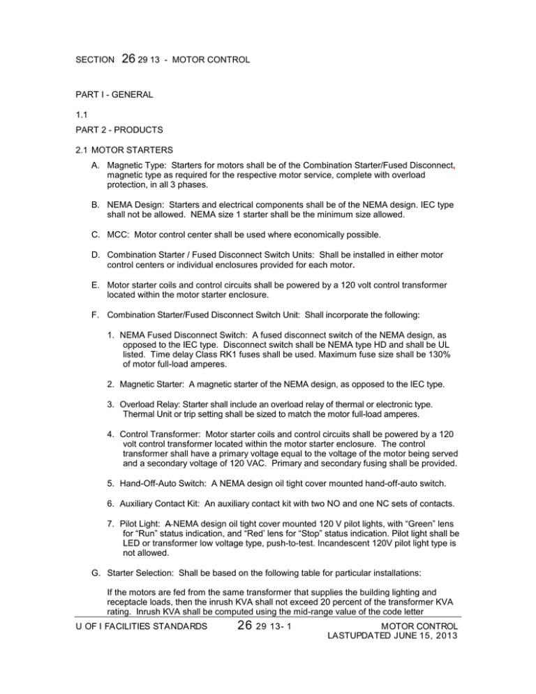
SECTION 26 29 13 - MOTOR CONTROL PART I - GENERAL 1.1 PART 2 - PRODUCTS 2.1 MOTOR STARTERS A. Magnetic Type: Starters for motors shall be of the Combination Starter/Fused Disconnect, magnetic type as required for the respective motor service, complete with overload protection, in all 3 phases. B. NEMA Design: Starters and electrical components shall be of the NEMA design. IEC type shall not be allowed. NEMA size 1 starter shall be the minimum size allowed. C. MCC: Motor control center shall be used where economically possible. D. Combination Starter / Fused Disconnect Switch Units: Shall be installed in either motor control centers or individual enclosures provided for each motor. E. Motor starter coils and control circuits shall be powered by a 120 volt control transformer located within the motor starter enclosure. F. Combination Starter/Fused Disconnect Switch Unit: Shall incorporate the following: 1. NEMA Fused Disconnect Switch: A fused disconnect switch of the NEMA design, as opposed to the IEC type. Disconnect switch shall be NEMA type HD and shall be UL listed. Time delay Class RK1 fuses shall be used. Maximum fuse size shall be 130% of motor full-load amperes. 2. Magnetic Starter: A magnetic starter of the NEMA design, as opposed to the IEC type. 3. Overload Relay: Starter shall include an overload relay of thermal or electronic type. Thermal Unit or trip setting shall be sized to match the motor full-load amperes. 4. Control Transformer: Motor starter coils and control circuits shall be powered by a 120 volt control transformer located within the motor starter enclosure. The control transformer shall have a primary voltage equal to the voltage of the motor being served and a secondary voltage of 120 VAC. Primary and secondary fusing shall be provided. 5. Hand-Off-Auto Switch: A NEMA design oil tight cover mounted hand-off-auto switch. 6. Auxiliary Contact Kit: An auxiliary contact kit with two NO and one NC sets of contacts. 7. Pilot Light: A NEMA design oil tight cover mounted 120 V pilot lights, with “Green” lens for “Run” status indication, and “Red’ lens for “Stop” status indication. Pilot light shall be LED or transformer low voltage type, push-to-test. Incandescent 120V pilot light type is not allowed. G. Starter Selection: Shall be based on the following table for particular installations: If the motors are fed from the same transformer that supplies the building lighting and receptacle loads, then the inrush KVA shall not exceed 20 percent of the transformer KVA rating. Inrush KVA shall be computed using the mid-range value of the code letter U OF I FACILITIES STANDARDS 26 29 13- 1 MOTOR CONTROL LASTUPDATED JUNE 15, 2013 designation of the motor. A table showing the maximum horsepower permitted for different size transformers based on motors with a code letter "G" has been supplied as a sample. Code "G" has a mid-range value of 6 KVA per horsepower. KVA of Transformer 100 225 300 500 750 1000 Maximum Acrossthe-Line HP 5 7-1/2 10 5 25 30 H. Reduced Voltage Starters: For motors over 50HP, provide reduced voltage starters Use part winding, wye-delta, or electronic type, as approved by University of Illinois F&S Department, to reduce locked rotor starting current to approximately 60% of full winding locked rotor current while providing approximately 50% of full winding locked rotor torque. For variable frequency drive applications see Section 26-29-23. I. Motors configured in duplex applications require 2 electrical circuits to each duplex control panel. Control circuits for each motor shall be capable of operating independently and shall be fed from their respective power circuits. Control transformers shall be provided as needed to limit control voltage to 120 volts. Single electrical feeds to dual motor systems are expressly prohibited. J. Power Quality: [Note to AE: Project Electrical Engineer shall direct special attention to power quality issues relating to power line disturbances caused by starting or operating large electrical loads. The final electrical design shall address power quality by the use of reduced voltage starters, electronic "soft start" solid state starters, or any other necessary means.] PART 3 - EXECUTION 3.1 END OF SECTION 26 29 13 This section of the U of I Facilities Standards establishes minimum requirements only. It should not be used as a complete specification. U OF I FACILITIES STANDARDS 26 29 13- 2 MOTOR CONTROL LASTUPDATED JUNE 15, 2013


