572 Indicator LED
advertisement

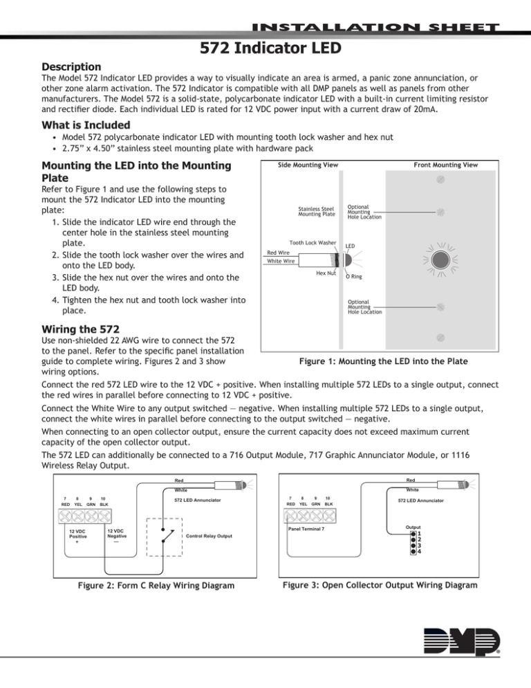
Installation Sheet 572 Indicator LED Description The Model 572 Indicator LED provides a way to visually indicate an area is armed, a panic zone annunciation, or other zone alarm activation. The 572 Indicator is compatible with all DMP panels as well as panels from other manufacturers. The Model 572 is a solid-state, polycarbonate indicator LED with a built‑in current limiting resistor and rectifier diode. Each individual LED is rated for 12 VDC power input with a current draw of 20mA. What is Included • Model 572 polycarbonate indicator LED with mounting tooth lock washer and hex nut • 2.75” x 4.50” stainless steel mounting plate with hardware pack Mounting the LED into the Mounting Plate Refer to Figure 1 and use the following steps to mount the 572 Indicator LED into the mounting plate: 1.Slide the indicator LED wire end through the center hole in the stainless steel mounting plate. 2.Slide the tooth lock washer over the wires and onto the LED body. 3.Slide the hex nut over the wires and onto the LED body. 4.Tighten the hex nut and tooth lock washer into place. Side Mounting View Stainless Steel Mounting Plate Tooth Lock Washer Front Mounting View Optional Mounting Hole Location LED Red Wire White Wire Hex Nut O Ring Optional Mounting Hole Location Wiring the 572 Use non-shielded 22 AWG wire to connect the 572 to the panel. Refer to the specific panel installation Figure 1: Mounting the LED into the Plate guide to complete wiring. Figures 2 and 3 show wiring options. Connect the red 572 LED wire to the 12 VDC + positive. When installing multiple 572 LEDs to a single output, connect the red wires in parallel before connecting to 12 VDC + positive. Connect the White Wire to any output switched — negative. When installing multiple 572 LEDs to a single output, connect the white wires in parallel before connecting to the output switched — negative. When connecting to an open collector output, ensure the current capacity does not exceed maximum current capacity of the open collector output. The 572 LED can additionally be connected to a 716 Output Module, 717 Graphic Annunciator Module, or 1116 Wireless Relay Output. Red Red White White 7 RED 8 YEL 9 GRN 12 VDC Positive + 10 BLK 12 VDC Negative — 572 LED Annunciator 7 RED 8 YEL 9 GRN Panel Terminal 7 Control Relay Output Figure 2: Form C Relay Wiring Diagram 10 BLK 572 LED Annunciator Output 1 2 3 4 Figure 3: Open Collector Output Wiring Diagram Installing the 572 onto a Backbox The mounting plate is designed to easily install on any standard single-gang backbox. Use the two single-slot screws to install the mounting plate directly onto the backbox. When the mounting hole locations do not align directly with the backbox mounting holes, refer to Figure 4 and use the angled mounting bracket to install the 572 and mounting plate. 1.Use the two Phillips head screws to install the angled mounting bracket onto the backbox. 2.Use the two single-slot screws to install the 572 and mounting plate onto the angled mounting bracket. Backbox 572 LED and Mounting Plate Angled Mounting Bracket Programming the 572 Refer to the specific panel programming guide to activate the 572 LED output operation. Two Phillips Screws Mount Bracket to Backbox Two Flat Head Screws Mount 572 Plate to Bracket 800 - 641 - 4282 Intrusion • fire • Access • Networks www.dmp.com 2500 North Partnership Boulevard Designed, Engineered and Assembled in U.S.A. S p r i n g fi e l d , M i s s o u r i 6 5 8 0 3 - 8 8 7 7 12175 LT-0808 © 2012 Digital Monitoring Products, Inc. Figure 4: Using the Angled Bracket to Install the LED and Plate onto a Backbox

