the product datasheet
advertisement
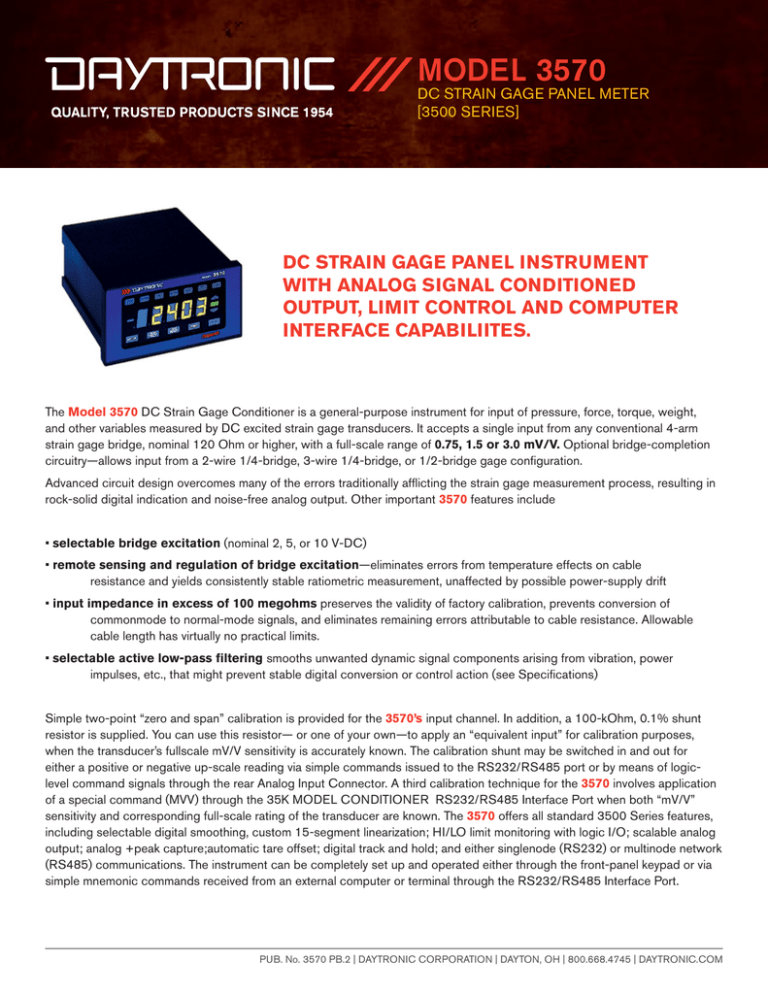
MODEL 3570 DC STRAIN GAGE PANEL METER [3500 SERIES] DC STRAIN GAGE PANEL INSTRUMENT WITH ANALOG SIGNAL CONDITIONED OUTPUT, LIMIT CONTROL AND COMPUTER INTERFACE CAPABILIITES. The Model 3570 DC Strain Gage Conditioner is a general-purpose instrument for input of pressure, force, torque, weight, and other variables measured by DC excited strain gage transducers. It accepts a single input from any conventional 4-arm strain gage bridge, nominal 120 Ohm or higher, with a full-scale range of 0.75, 1.5 or 3.0 mV/V. Optional bridge-completion circuitry—allows input from a 2-wire 1/4-bridge, 3-wire 1/4-bridge, or 1/2-bridge gage configuration. Advanced circuit design overcomes many of the errors traditionally afflicting the strain gage measurement process, resulting in rock-solid digital indication and noise-free analog output. Other important 3570 features include • selectable bridge excitation (nominal 2, 5, or 10 V-DC) • remote sensing and regulation of bridge excitation—eliminates errors from temperature effects on cable resistance and yields consistently stable ratiometric measurement, unaffected by possible power-supply drift • input impedance in excess of 100 megohms preserves the validity of factory calibration, prevents conversion of commonmode to normal-mode signals, and eliminates remaining errors attributable to cable resistance. Allowable cable length has virtually no practical limits. • selectable active low-pass filtering smooths unwanted dynamic signal components arising from vibration, power impulses, etc., that might prevent stable digital conversion or control action (see Specifications) Simple two-point “zero and span” calibration is provided for the 3570’s input channel. In addition, a 100-kOhm, 0.1% shunt resistor is supplied. You can use this resistor— or one of your own—to apply an “equivalent input” for calibration purposes, when the transducer’s fullscale mV/V sensitivity is accurately known. The calibration shunt may be switched in and out for either a positive or negative up-scale reading via simple commands issued to the RS232/RS485 port or by means of logiclevel command signals through the rear Analog Input Connector. A third calibration technique for the 3570 involves application of a special command (MVV) through the 35K MODEL CONDITIONER RS232/RS485 Interface Port when both “mV/V” sensitivity and corresponding full-scale rating of the transducer are known. The 3570 offers all standard 3500 Series features, including selectable digital smoothing, custom 15-segment linearization; HI/LO limit monitoring with logic I/O; scalable analog output; analog +peak capture;automatic tare offset; digital track and hold; and either singlenode (RS232) or multinode network (RS485) communications. The instrument can be completely set up and operated either through the front-panel keypad or via simple mnemonic commands received from an external computer or terminal through the RS232/RS485 Interface Port. PUB. No. 3570 PB.2 | DAYTRONIC CORPORATION | DAYTON, OH | 800.668.4745 | DAYTRONIC.COM MODEL 3570 DC STRAIN GAGE PANEL METER [3500 SERIES] SPECIFICATIONS: Input Type: Conventional 4-arm strain gage bridge, nominal Offset: Initial: ±0.025% of full scale; vs. Temperature: ±25 120 Ohms or higher NOTE: 1/4- and 1/2-bridge gage configurations can be accomplished by means of the Model 10CJB-2 Bridge Completion Card, or by equivalent external bridge completion circuitry supplied by the user. ppm/°C; vs. Time: ±10 ppm/month Input Ranges (full-scale)*: ppm/month Gain Accuracy: ±0.02% of full scale ± 1 count LSD, typical, following calibration** Gain Stability: Vs. Temperature: ±50 ppm/°C; vs. Time: ±20 1 Actual Absolute Input at which 2 Nominal Normal-Mode Maximum Display Reading 3 Input Input-Signal Overrange Corresponds Full-Scale Range: ±5 V nominal; ±8 V maximum Range is scalable in 0.1% increments between 74.5% and 125.5% of nominal input. 4 Range Voltage (Max) (50%) to “m” Term Allowable Loading: 5 mA, maximum 1 2 Analog Output 3 4 3.0 mV/V 45 mV 4.5 mV/V 4.0 mV/V 1.5 mV/V 22.5 mV 2.25 mV/V 2.0 mV/V 0.75 mV/V 11.25 mV 1.125 mV/V 1.0 mV/V Operating Temperature: 0° C to +50°C (+32° F to +122° F) Storage Temperature: -40°C to +80°C (-40° F to +176° F) Operating Humidity Range: 10 to 95% max., noncondensing Instrument Weight: 3.25 lb (1.47 kg), approximate Dimensions: 5.68” W x 2.84” H x 7.06” D Power Voltage: 90-265 V-AC (eliminates the need to convert between 110-V and 220-V levels) Frequency: 50-400 Hz Consumption: 10 W max. Offset Range Adjustment: ±25.5% in 0.1% increments Offset Accuracy: 0.1% maximum Span Accuracy: 0.2% maximum Offset and Span Drift: ±50 ppm/°C; ±20 ppm/month Configuration: Single-ended, return to System Common Analog Filtering: Fixed: 2 kHz; Selectable: 5-pole filter with selectable low- pass corner frequency of 5, 10, or 20 Hz Corner Frequency Response at . . . 5 Hz 10 Hz 20 Hz -3 dB 5 Hz 10 Hz 20 Hz -60 dB 32 Hz 65 Hz 125 Hz Step Response Settling Time (Full-Scale Output) 5 Hz 10 Hz 20 Hz Display: 5-digit LCD reflective, non-light-emitting To 1% of final value 250 ms 125 ms 60 ms A/D Conversion: 16-bit; approximately 1-kHz conversion rate; transparent autocalibration every 2 seconds To 0.1% of final value 400 ms 200 ms 100 ms To 0.02% of final value 600 ms 300 ms 170 ms Excitation Supplied: Selectable 10, 5, or 2 V-DC; 85 mA max. Normal-Mode Range: ±45 mV operating; ±8 V without instrument damage Common-Mode Range: ±0.50 V operating; ±8 V without instrument damage Common-Mode Rejection Ratio: -60 dB at DC; -90 dB at 60 Peak Capture: Positive analog peak, digitally held for indefinite display; minimum full-scale input pulse duration is 6 msec (to 1% of full-scale accuracy), 12 msec (to 0.1% of fullscale accuracy), and 20 msec (to 0.02% of full-scale accuracy); PEAK and TRACK modes controlled by front-panel button, rear-panel logic input (see Fig. 35.6), or computerport command Hz, 1 kHz, and 3 kHz Input Impedance (Differential and Common-Mode): Greater than 100 M Ohm PUB. No. 3570 PB.2 | DAYTRONIC CORPORATION | DAYTON, OH | 800.668.4745 | DAYTRONIC.COM
