Heavy Duty Emergency Stop – Type GLES Guardian Line E Stop
advertisement

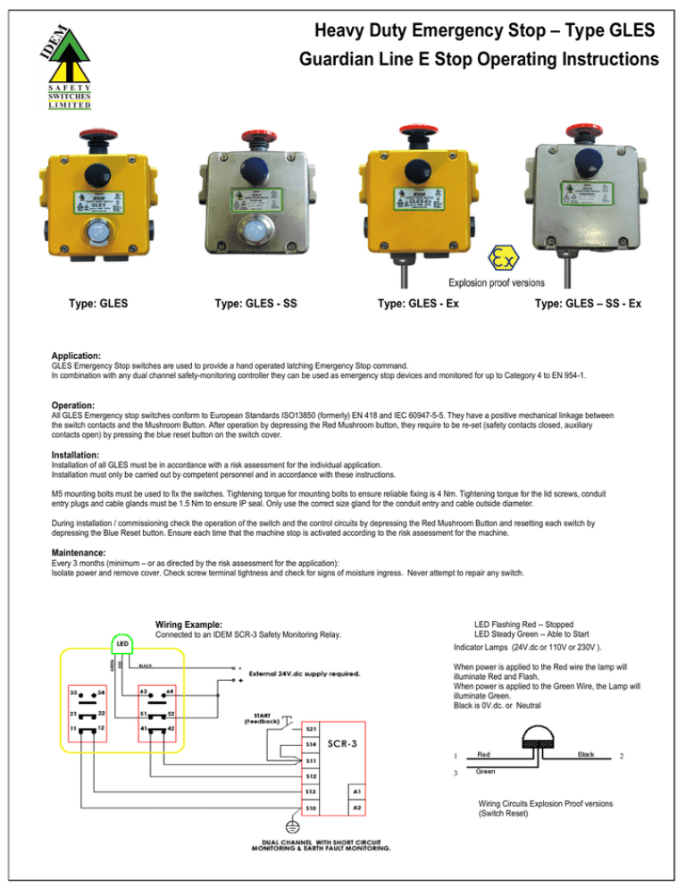
Heavy Duty Emergency Stop – Type GLES Guardian Line E Stop Operating Instructions Type: GLES Type: GLES - SS Type: GLES - Ex Type: GLES – SS - Ex Application: GLES Emergency Stop switches are used to provide a hand operated latching Emergency Stop command. In combination with any dual channel safety-monitoring controller they can be used as emergency stop devices and monitored for up to Category 4 to EN 954-1. Operation: All GLES Emergency stop switches conform to European Standards ISO13850 (formerly) EN 418 and IEC 60947-5-5. They have a positive mechanical linkage between the switch contacts and the Mushroom Button. After operation by depressing the Red Mushroom button, they require to be re-set (safety contacts closed, auxiliary contacts open) by pressing the blue reset button on the switch cover. Installation: Installation of all GLES must be in accordance with a risk assessment for the individual application. Installation must only be carried out by competent personnel and in accordance with these instructions. M5 mounting bolts must be used to fix the switches. Tightening torque for mounting bolts to ensure reliable fixing is 4 Nm. Tightening torque for the lid screws, conduit entry plugs and cable glands must be 1.5 Nm to ensure IP seal. Only use the correct size gland for the conduit entry and cable outside diameter. During installation / commissioning check the operation of the switch and the control circuits by depressing the Red Mushroom Button and resetting each switch by depressing the Blue Reset button. Ensure each time that the machine stop is activated according to the risk assessment for the machine. Maintenance: Every 3 months (minimum – or as directed by the risk assessment for the application): Isolate power and remove cover. Check screw terminal tightness and check for signs of moisture ingress. Never attempt to repair any switch. Wiring Example: LED Flashing Red -- Stopped LED Steady Green -- Able to Start Connected to an IDEM SCR-3 Safety Monitoring Relay. Indicator Lamps (24V.dc or 110V or 230V ). When power is applied to the Red wire the lamp will illuminate Red and Flash. When power is applied to the Green Wire, the Lamp will illuminate Green. Black is 0V.dc. or Neutral 1 2 3 Wiring Circuits Explosion Proof versions (Switch Reset) Heavy Duty Emergency Stop – Type GLES Standards: Enclosure / Cover IP Rating Mounting Mounting position Conduit entries Torque settings Ambient Temperature Vibration resistance Shock resistance Mechanical Life Approx. weight Contact Material Termination Rating Operational Rating Thermal Current (Ith) Rated Insulation Voltage (Ui) Withstand Voltage (Uimp) Short Circuit Overload Protection IEC 947-5-1 IEC947-5-5 EN 418 UL508 Die-Cast – Painted Yellow or Stainless Steel 316 IP67 4 x M5 Any 3 x M20 or 3 x ½ “ NPT by part number Mounting M5 4.0 Nm Lid Torx T20 M4 1.5 Nm Terminals 1.0 Nm -25C. 80 C. -40C. 80C. FZ versions 10-500Hz 0.35mm 15g 11ms 1,000,000 operations 1000 g. Yellow 2000g. S/Steel IEC 60947-5-1 Double break Type Zb up to 4NC (positive break) up to 2NO (Auxiliary) Silver Clamp up to 2.5 sq. mm conductors Utilisation Category : AC15 A300 240V. 3A. 10A. 500V. 2500V. Fuse Externally 10A. (F) Exd IIC T6 (-20 ≤ Ta ≤ + 60C) Gb Exd tb IIIC T85C (-20 ≤ Ta ≤ + 60C) Db IDEM SAFETY SWITCHES Ltd., 2 Ormside Close, Hindley Industrial Estate, Hindley Green, Wigan, WN2 4HR UK. Tel: +44 (0)1942 257070 Fax.: +44 (0)1942 257076 IDEM (USA) 4075 Papazian Way, Suite 105, Fremont, CA 94538 Tel:510-445-0751 Fax:1866-431-7064 email: sales@idemsafety.com Web: www.idemsafety.com Doc: 102533 June 2012


