SP.764, Practical Electronics Dr. James A. Bales Lecture 5: Relays
advertisement

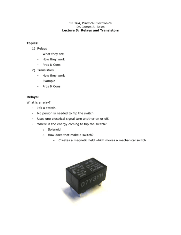
SP.764, Practical Electronics Dr. James A. Bales Lecture 5: Relays and Transistors Topics: 1) Relays - What they are - How they work - Pros & Cons 2) Transistors - How they work - Example - Pros & Cons Relays: What is a relay? - It’s a switch. - No person is needed to flip the switch. - Uses one electrical signal turn another on or off. - Where is the energy coming to flip the switch? o Solenoid o How does that make a switch? Creates a magnetic field which moves a mechanical switch. - Electromechanical relay rated to a few thousand volts. o If current flows through the solenoid, the switch makes contact. o Two independent circuits: COIL and CONTACT. COIL COIL Normally Open Contact (NO) Normally Closed Contact (NC) Schematic: COIL + - CONTACT NO NC Single Pole Double Throw (SPDT) Relay Specifications: - For our relay: o Coil takes o 5V & 20mA = 100mW Contacts can handle 30V & 2A = 60W SP.764, Practical Electronics Dr. James A. Bales Lecture 5 Page 2 of 6 Coil Contact Nominal Voltage Max Voltage Resistance Max Current Current “Pick-Up” Voltage or Current “Hold” Needed to maintain position Needed to move switch +5V OSCILLATOR + + - A better representation of the relay includes a diode. The diode eliminates voltage spikes produced by the inductor when current suddenly stops flowing. An oscillator can be created by tying the + side of the coil with the Normally Closed contact together, and powering the contact with 5 volts. Pros: - Electrical Isolation: No electrical connection between coil and contact sides. - High Voltage & Current (on contact side) Cons: - Power Lost in Coil - Size: Big and bulky. - SLOW! - Expensive SP.764, Practical Electronics Dr. James A. Bales Lecture 5 Page 3 of 6 Transistors: - The first transistor was developed by William Shockley and John Bardeen. - Transistors are semiconductor devices. - What do they look like? -OR- Bottom View Schematic Collector 123 Base 1 = EMITTER 2 = BASE Emitter 3 = COLLECTOR C IC ↓ Measurable V’s & I’s - VCB = VC-VB (Collector to Base) - VBE = VB-VE (Base to Emitter) - VCE = VC-VE (Collector to Emitter) IB → B IE ↓ E SP.764, Practical Electronics Dr. James A. Bales Lecture 5 Page 4 of 6 Rule 1: IC = β I B constant for the transistor Value = 10 to 200. Transistor gives current gain. ∴ I E = I B + I C = ( β + 1) I B Rule 2: If IB > 0 VBE 0.6V (i.e. the base-emitter junction looks like a diode) Analysis: Assume I B > 0, then VBE = 0.6V = VB − VE 0 ⇒ VB = 0.6V Current through 100Ω resistor is: I= ∆V 5V − 0.6V = = 0.044 A = 44 mA R 100Ω SP.764, Practical Electronics Dr. James A. Bales Lecture 5 Page 5 of 6 Then, I C = β I B = 4.4 A !! Lamp limits IC IC Load is saturated IC Transistor limits IC Slope = β IB VCE 5V VCE ≈ 0.2V (saturation) IB Pros: - Small and handy - Cheap - FAST! Cons: - No Electrical Isolation - Cannot work with High Voltages & Currents SP.764, Practical Electronics Dr. James A. Bales Lecture 5 Page 6 of 6


