Monitoring Relays
advertisement

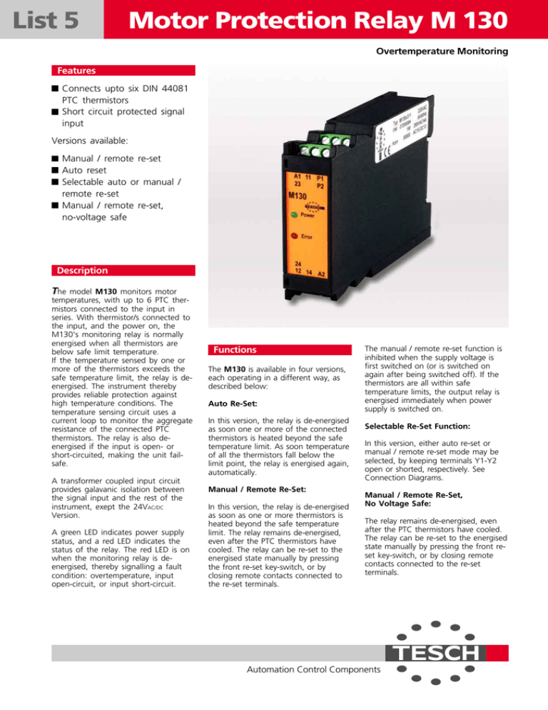
List 5 Motor Protection Relay M 130 Overtemperature Monitoring Features Connects upto six DIN 44081 PTC thermistors Short circuit protected signal input Versions available: Manual / remote re-set Auto reset Selectable auto or manual / remote re-set Manual / remote re-set, no-voltage safe Description The model M130 monitors motor temperatures, with up to 6 PTC thermistors connected to the input in series. With thermistor/s connected to the input, and the power on, the M130's monitoring relay is normally energised when all thermistors are below safe limit temperature. If the temperature sensed by one or more of the thermistors exceeds the safe temperature limit, the relay is deenergised. The instrument thereby provides reliable protection against high temperature conditions. The temperature sensing circuit uses a current loop to monitor the aggregate resistance of the connected PTC thermistors. The relay is also deenergised if the input is open- or short-circuited, making the unit failsafe. A transformer coupled input circuit provides galavanic isolation between the signal input and the rest of the instrument, exept the 24VAC/DC Version. A green LED indicates power supply status, and a red LED indicates the status of the relay. The red LED is on when the monitoring relay is deenergised, thereby signalling a fault condition: overtemperature, input open-circuit, or input short-circuit. Functions The M130 is available in four versions, each operating in a different way, as described below: Auto Re-Set: In this version, the relay is de-energised as soon one or more of the connected thermistors is heated beyond the safe temperature limit. As soon temperature of all the thermistors fall below the limit point, the relay is energised again, automatically. Manual / Remote Re-Set: In this version, the relay is de-energised as soon as one or more thermistors is heated beyond the safe temperature limit. The relay remains de-energised, even after the PTC thermistors have cooled. The relay can be re-set to the energised state manually by pressing the front re-set key-switch, or by closing remote contacts connected to the re-set terminals. The manual / remote re-set function is inhibited when the supply voltage is first switched on (or is switched on again after being switched off). If the thermistors are all within safe temperature limits, the output relay is energised immediately when power supply is switched on. Selectable Re-Set Function: In this version, either auto re-set or manual / remote re-set mode may be selected, by keeping terminals Y1-Y2 open or shorted, respectively. See Connection Diagrams. Manual / Remote Re-Set, No Voltage Safe: The relay remains de-energised, even after the PTC thermistors have cooled. The relay can be re-set to the energised state manually by pressing the front reset key-switch, or by closing remote contacts connected to the re-set terminals. Automation Control Components The right to make changes is reserved Motor Protection Relay M 130 Specifications Dimensions 0.8 to 1.1 of rated voltage 50 /60 Hz Approx. 1 VA 107 switching cycles < 0.01 % / °K - 5 ° C to 60 ° C, (no condensation) < 20 ms < 20 ms 250 V Overvoltage category III per VDE 0100 Pollution level 2 2000 V per VDE 0435 IP 20 terminals, IP 40 casing Per DIN VDE 0470-1 (11/92) Screw type with protective cover 2.5 mm² fine stranded wire, max. 7.0 mm stripped AC15 250 V 4 A, DC13 24 V 3 A Test voltage Mode of protection Connecting terminals Conductor size Relay contacts rating Switching thresholds: Relay de-energisation point Relay energisation point Weight 75 22.5 110 Voltage range Frequency range Power consumption Relay mechanical life Temperature effect Operating temperature Response time Re-set time Isolation voltage Creep and air paths DIN rail mounting to EN 50022-35 x 7,5 > 2,5 k ...3,6 k and short circuit < 1,5 k ...2,3 k Approx. 125 g Connection Diagram DIN 44081 Reset DIN 44081 PTC A1 11 A1 P1 11 12 11 S1 A1 S1 P1 PTC A1 23 P1 P2 11 (23) A1 M130 P2 14 12 14 A2 A2 (24) 12 Auto re-set, 1 Changeover contact Terminals configuration depends on version DIN 44081 PTC A1 (23) P1 P2 M130 A2 Reset 11 S1 S1 P1 P1 P2 11 23 12 14 24 M130 P2 12 14 14 (24) A2 Y1 Y2 P2 24 12 A2 Manual / remote re-set / 1Changeover contact ( No - voltage safe / 1Changeover contact, 1 Normally open contact ) Y1 14 Y2 A2 Y1-Y2 Shorted = Manual / remote re-set Y1-Y2 Open = Auto re-set 1 Changeover contact, 1 Normally open contact Models and Ordering Data Operating Voltage M130 with Short Circuit Protection Manual / remote re-set; 1 changeover contact Auto re-set; 1 changeover contact Manual / remote re-set, no-voltage safe, 1 changeover + 1 normally open contact Selectable re-set function, 1 changeover + 1 normally open contact TESCH GmbH Automatic Control Components Graefrather Straße 124 D-42329 Wuppertal 230 VAC 24 VAC/DC 07200276 07200280 07200284 115 VAC 24 VAC Order No. 07200277 07200278 07200281 07200282 07200285 07200286 07200288 07200289 07200291 Phone +49-2 02-73 91-0 Fax +49-2 02-73 91-115 07200290 07200279 07200283 07200287 http://www.tesch.de eMail: vertrieb-ak@tesch.de Other than the versions listed here, special versions can also be supplied at short notice. Germany

