Chapter 9
advertisement
Chapter 9: Sinusoidal Steady-State Analysis
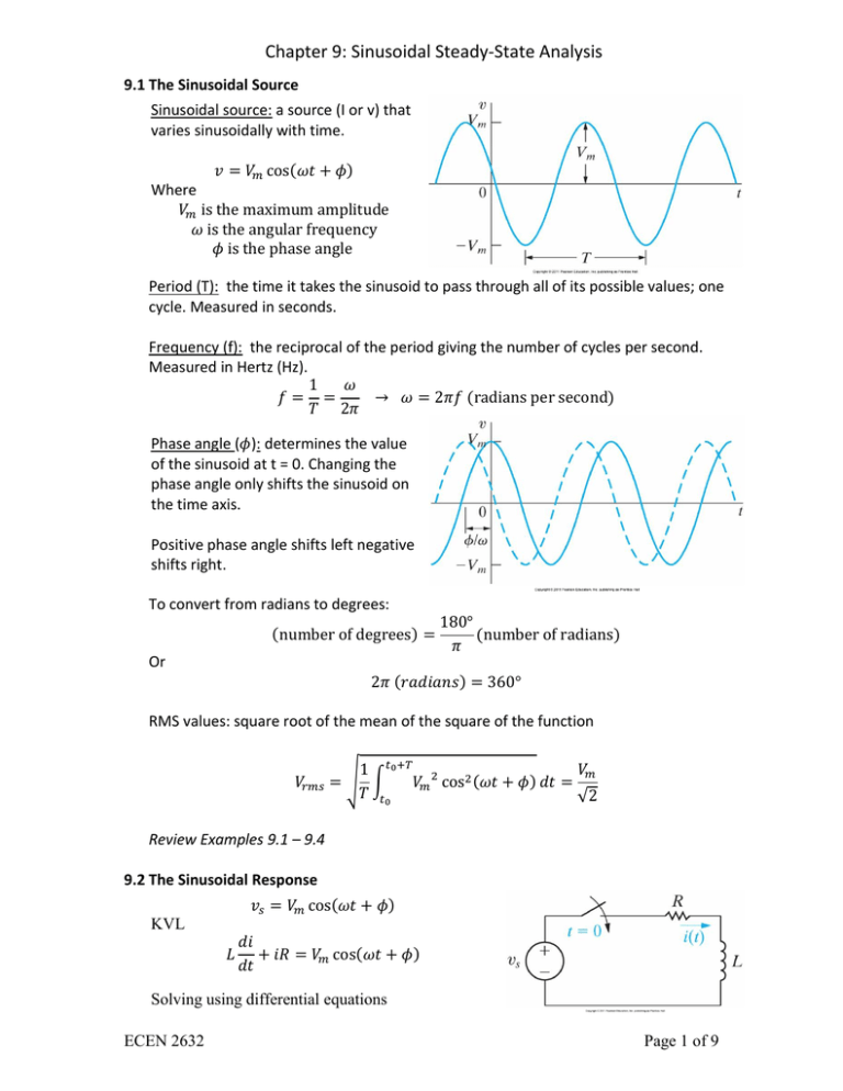
9.1 The Sinusoidal Source
Sinusoidal source: a source (I or v) that
varies sinusoidally with time.
Where
Period (T): the time it takes the sinusoid to pass through all of its possible values; one
cycle. Measured in seconds.
Frequency (f): the reciprocal of the period giving the number of cycles per second.
Measured in Hertz (Hz).
Phase angle ( ): determines the value
of the sinusoid at t = 0. Changing the
phase angle only shifts the sinusoid on
the time axis.
Positive phase angle shifts left negative
shifts right.
To convert from radians to degrees:
Or
RMS values: square root of the mean of the square of the function
√ ∫
√
Review Examples 9.1 – 9.4
9.2 The Sinusoidal Response
KVL
Solving using differential equations
ECEN 2632
Page 1 of 9
Chapter 9: Sinusoidal Steady-State Analysis
√
√
Where
√
And
√
Characteristics of the steady-state solution
1. It is a sinusoidal function
2. Frequency of the response is identical to the frequency of the source
3. The maximum amplitude of the response differs from the amplitude of the
source
4. The phase angle of the response differs from the phase angle of the source
9.3 The Phasor
Phasor: complex number that carries the magnitude and phase angle information of a
sinusoidal function
From Euler’s identity:
Where
{
}
{
}
.
Rewriting a sinusoid
{
}
{
}
Thus the phasor transform
{
}
The phasor is usually indicated by bold type or as a variable with an arrow above it ⃗
Note: the phasor transform transfers the function from the time domain to the complex
number domain known as the frequency domain.
The above transform is in polar coordinate form to express in rectangular form;
Often the polar expression is further abbreviated as follows
ECEN 2632
Page 2 of 9
Chapter 9: Sinusoidal Steady-State Analysis
Polar to Rectangular conversion
Rectangular to Polar conversion
√
(
)
Note: The phasor transform can only be performed on components with the same
frequency since the frequency information is not retained in the transform
The Inverse Phasor Transform
{
}
{
}
The phasor transform is useful in circuit analysis because it reduces the work of finding a
steady state response to algebra with complex numbers
Ex.
Review Example 9.5 and Assessment Problems 9.1 & 9.2
9.4 The Passive Circuit Elements in the Frequency Domain
V-I of Resistors
From Ohm’s Law
[
]
Note: there is no phase shift across the terminals of a resistor
V-I of Inductors
[
]
Note: there is a +90° phase shift across the terminals of an
ECEN 2632
Page 3 of 9
Chapter 9: Sinusoidal Steady-State Analysis
inductor. Voltage leads current or current lags voltage
V-I of Capacitors
(
)
Note: there is a -90° phase shift across the terminals of an inductor. Voltage lags
current or current leads voltage
Impedance and Reactance
Impedance: ratio of a circuit element’s voltage
phasor to its current phasor.
Reactance: imaginary part of the impedance
In general the V-I characteristic of any element
in the frequency domain can be expressed:
Where Z is the impedance of the circuit element
Note: Although the impedance is a complex number it is not a phasor. Thus all phasors
are complex numbers but all complex numbers are not phasors..
Review Assessment Problems 9.3 & 9.4
9.5 Kirchhoff’s Laws in the Frequency Domain
KVL in the frequency domain:
KCL in the frequency domain:
Thus the techniques used in the time domain are the same for phasors in the frequency
domain
Review Assessment Problems 9.5
ECEN 2632
Page 4 of 9
Chapter 9: Sinusoidal Steady-State Analysis
9.6 Series, Parallel and Delta-to-Wye Simplifications
Series impedances combine like series resistances
(add up)
Review Example 9.6 and Assessment Problem 9.6
Parallel impedances combine like parallel
resistances (inverse of the sum of the inverses)
Review Example 9.7 and Assessment Problems 9.7
& 9.8
Delta to Wye
Wye to Delta
Review Example 9.8 and Assessment Problem 9.9
9.7 Source Transformations and Thevenin-Norton Equivalent Circuits
Source Transformations
Thevenin and Norton Equivalents
Review Examples 9.9 & 9.10 and Assessment Problems 9.10 & 9.11
ECEN 2632
Page 5 of 9
Chapter 9: Sinusoidal Steady-State Analysis
9.8 The Node-Voltage Method
Performed the same as in the time domain only on frequency domain equivalent circuits
using Impedances
Review Example 9.11 and Assessment Problem 9.12
9.9 The Mesh-Current Method
Performed the same as in the time domain only on frequency domain equivalent circuits
using Impedances
Review Example 9.12 and Assessment Problem 9.13
9.10 The Transformer
A device based on magnetic coupling, formed when two coils are wound on a single
core. Linear transformers are used in communications; ideal transformers in power.
Primary winding - side
connected to the
source
Secondary winding side connected to the
load
Mesh equation of the circuit above
Substituting: (
is the total self-impedance in the primary coil;
the secondary coil)
Solving for the current:
The internal impedance as seen by the source:
ECEN 2632
Page 6 of 9
Chapter 9: Sinusoidal Steady-State Analysis
The impedance at the source terminals:
The last term shows effects of the transformer on the load impedance seen by the
source. Without a transformer the load would connect directly to the source and the
source would see an impedance of . This term is called the reflected impedance
and is due solely to the mutual inductance.
Expanding the reflected impedance for
|
|
[
]
Where
9.11 The Ideal Transformer
Transformer exhibiting the following properties:
1. Coefficient of coupling is unity (k = 1)
2. The self-inductance of each coil is infinite
3. The coil losses, due to parasitic resistance, are negligible
Transformers wound on ferromagnetic cores near this condition.
Determining Voltage and Current Ratios
From the first figure:
Combining the two
For unity coupling
√
√
ECEN 2632
;
Page 7 of 9
Chapter 9: Sinusoidal Steady-State Analysis
√
Therefore
Summing the voltages for the second circuit:
√
Therefore
Determining the Polarity of the Voltage and Current Ratios
If the coil voltages
and
are both positive or negative at the dot-marked
terminals, use a plus sign relating the voltages. Otherwise use a negative sign.
If the coil currents and are both directed into or out of the dot-marked
terminals, use a minus sign relating the currents. Otherwise use a plus sign.
Note: The turns-ratio can either be defined as
or
; this book uses the later and
defines
The Use of the Ideal Transformer for Impedance Matching
Using the turns ratio
The impedance seen by the source
Where
ECEN 2632
⁄
is equal to
Page 8 of 9
Chapter 9: Sinusoidal Steady-State Analysis
9.12 Phasor Diagrams
Plotting a group of phasors:
(Magnitude and phase)
Comparing complex axis to
polar
Review Examples 9.15 & 9.16
ECEN 2632
Page 9 of 9
