Impedance Measurement – 3 Voltmeters Method
advertisement
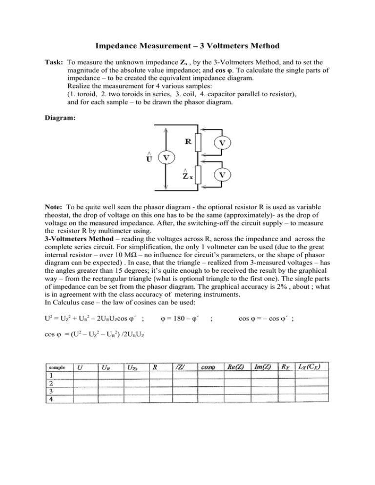
Impedance Measurement – 3 Voltmeters Method Task: To measure the unknown impedance Zx , by the 3-Voltmeters Method, and to set the magnitude of the absolute value impedance; and cos φ. To calculate the single parts of impedance – to be created the equivalent impedance diagram. Realize the measurement for 4 various samples: (1. toroid, 2. two toroids in series, 3. coil, 4. capacitor parallel to resistor), and for each sample – to be drawn the phasor diagram. Diagram: Note: To be quite well seen the phasor diagram - the optional resistor R is used as variable rheostat, the drop of voltage on this one has to be the same (approximately)- as the drop of voltage on the measured impedance. After, the switching-off the circuit supply – to measure the resistor R by multimeter using. 3-Voltmeters Method – reading the voltages across R, across the impedance and across the complete series circuit. For simplification, the only 1 voltmeter can be used (due to the great internal resistor – over 10 MΩ – no influence for circuit’s parameters, or the shape of phasor diagram can be expected) . In case, that the triangle – realized from 3-measured voltages – has the angles greater than 15 degrees; it’s quite enough to be received the result by the graphical way – from the rectangular triangle (what is optional triangle to the first one). The single parts of impedance can be set from the phasor diagram. The graphical accuracy is 2% , about ; what is in agreement with the class accuracy of metering instruments. In Calculus case – the law of cosines can be used: U2 = UZ2 + UR2 – 2URUZcos φ´ ; cos φ = (U2 – UZ2 – UR2) /2URUZ φ = 180 – φ´ ; cos φ = – cos φ´ ;

