SF6 Gas Insulated Switchgear
advertisement
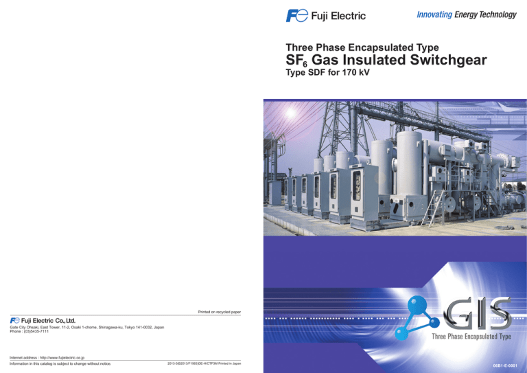
Three Phase Encapsulated Type SF6 Gas Insulated Switchgear Type SDF for 170 kV Printed on recycled paper Gate City Ohsaki, East Tower, 11-2, Osaki 1-chome, Shinagawa-ku, Tokyo 141-0032, Japan Phone : (03)5435-7111 Internet address : http://www.fujielectric.co.jp Information in this catalog is subject to change without notice. 2013-3(B2013/F1983)DE-H/CTP3M Printed in Japan 06B1-E-0001 With Trustworthy Technology, Structure Fuji Electric as a manufacturer of comprehensive substation equipment is ready to supply advanced SF6 gas insulated switchgear (GIS) superior in reliability, disaster prevention, safety and environmental harmony. Installation of SF6 insulated switchgear has very largely increased all over the world, because of the advantages: ● Small space requirement ● High reliability ● Safety ● Environment compatibility ● Long maintenance intervals ● Minimum erection period at site Fuji alone has installed a great number of switch bays for 72.5 kV to 300 kV since 1970, both at home and abroad. The three phase encapsulated switchgear for 72.5 kV was developed in 1975 and since then the installation of SF6 switchgear has increased rapidly. After three years in 1978, Fuji has put into operation the first three phase encapsulated SF6 switchgear for 170 kV in the world. On the excellent experience of SF6 switchgear, Fuji has a compact and reliable three phase encapsulated SF6 switchgear : type SDF. Characteristic features Small overall dimensions Section of a cable feeder bay with double busbar The modular design principle applied make for minimum space requirements and very low profile needs very little vertical clearance. Hence the costs of foundations and buildings can be reduced. Voltage transformer Maintenance earthing switch permits quantity production and the use of standard parts, which increase reliability and simplifies stock-keeping. Current transformer Line disconnector Make-proof earthing switch The fully earthed enclosure The steel enclosure used protects the operating personnel and prevents HF interference. There is no risk of touching live parts and also atmospheric pollution. is highly resistant to arcing and affords the personnel optimum protection. A further advantage of the steel enclosure is their high mechanical strength. Unified SF6 gas pressure Long service life throughout the switchgear makes simplified gas maintenance work. of the switchgear is expected due to nonoxidizing of SF6 gas in enclosure and oil in electro-hydraulic operating mechanism. Circuit breaker Bus disconnector Bus disconnector Control box for GIS Cable sealing end Maintenance earthing switch Operating box for curcuit breaker Technical data Surge arrester Busbar Busbar Switchgear type SDF120 Rated voltage [kV] 170 Rated power-frequency withstand voltage [kV] 325 Rated lightning impulse withstand voltage [kV] 750 Rated normal current [A] 1250/2000/4000 Rated short-circuit breaking current [kA] 40 Rated short-time withstand current (3 s) [kA] 40 Rated peak withstand current [kA] 100(50 Hz), 104(60 Hz) Rated SF6 gas pressure, gauge (at 20 ℃) Switchgear [MPa] 0.5 Circuit breaker [MPa] 0.5 Rated break time of circuit breaker [cycles] 3 Rated operating sequence of circuit breaker (standard) O-3 min.-CO-3 min.-CO CO-15 s-CO O-0.3 s-CO-3 min.-CO Single line diagram Voltage transformer Busbar Bus disconnector Circuit breaker Line disconnector Bus disconnector Cable sealing end (Supplied by cable supplier) Surge arrester Busbar Maintenance earthing switch 1 Current transformer Maintenance earthing switch Make-proof earthing switch 2 Circuit Breaker The earthed housing accommodates three phase interrupters fixed on supporting mounts. At the lower part of circuit breaker, the operating box is arranged, which accommodates hydraulic operating mechanism and monitoring unit for the circuit breaker. The interrupter has a double-flow system and the compressed SF6 gas, which is produced by the downward movement of the puffer cylinder at opening, flows into both directions in order to distinguish effectively the arc generated at arcing contacts. The moving section is composed of nozzle, moving contact, and a moving cylinder connected to hydraulic operating mechanism through insulating rod and cylinder rod mechanically. The current path is composed of upper connecting conductor, fixed contact support, main contact, moving contact, support and lower connecting conductor. Circuit breaker Upper connecting conductor Earthed housing Three phase interrupters Nozzle Arcing contacts Oil pump, oil tank, main valve, auxiliary valves, pressure switches and gauges are incorporated as one block unit and connected directly to main cylinder. Hence a compact, very reliable and pipeless hydraulic operating mechanism was realized. The valve seal of oil system is made of metal seat and metal ball, which is good for permanent use without necessity of replacement. But the valve seal of air system is made of rubber, which degrades its quality and requires replacement periodically. Hydraulic operating mechanism Interrrupter Main contact Moving contact Lower connecting conductor Puffer cylinder Support Insulating rod Control box for GIS Closing Supporting mounts Closing coil energized Pilot valve opens. Main valve opens. Main cylinder moves. Opening Cylinder rod Trip coil energized Accumulator Pilot valve closes. N2 Main valve closes. Operating box for circuit breaker Main cylinder moves. 31.5 Mpa 0MPa Closing coil Pilot valve Trip coil Closed position Opening Opening (arc quenching) SF6 gas in puffer cylinder is SF6 gas flows during arc compressed. quenching. Closing Principle of arc quenching Open position Opening Thousands of Fuji SF6 circuit breakers with hydraulic operating mechanism were delivered into all over the world and have been in satisfactory operation since 1973. The SF6 switchgear SDF is equipped with the single pressure puffer type gas circuit breaker with hydraulic operating mechanism which is used uniformly also for outdoor circuit breakers. Fuji gas circuit breakers have the advantages: ● Low noise level during operation ● Excellent interrupting performance ● Long maintenance intervals ● Individual energy supply, no air-compressor necessary Hydraulic Operating Mechanism Oil tank M Main cylinder P Aux.switch Main valve Aux.cylinder 3 Hydraulic unit 4 Other Components Disconnectors and earthing switches There are two kinds of disconnectors employed in the switchgear: the linear type disconnector provided in a linear current passage, and the right-angled type disconnector provided at right-angle of the current passage. Line disconnector is of linear type and is incorporated together with earthing switch in one housing as a combined disconnector/earthing switch. Bus disconnector is of right-angled type and is assembled in each bus enclosure. Disconnectors and earthing switches are normally motor-and manual-operated. When disconnectors are specified to have a switching capability of small current as charging current and transformer magnetizing current, they are operated by the motorcharged spring mechanism. The make-proof earthing switch is provided with the motorcharged spring mechanism. Earthed side of the earthing switch is brought out from the earthed metal housing and earthed to it through a removable bolted link for primary injection test. SF6 Gas System Busbar The three phase conductors made of aluminum or copper, depending on the current rating, are supported by gas tight insulator (for standard bay bus) or individual supporting insulators (for extended bus). The three phase conductors are arranged in a rational disposition to reduce the intensity of electric field on the surface of lower part of enclosure and hence be reliable against the metallic dust, which can possibly enter during site erection. Extended bus [at 20 ℃ ] Operation lockout pressure [MPa] Circuit breakers 0.5 0.45 0.4 Disconnectors 0.5 earthing switches 0.45 (Note) Other components 0.5 0.45 ー Rated SF6 gas pressure [MPa] SF6 gas system VT CT DS ES ES Enclosure CB Pressure-temperature characteristic curve of SF6 gas LA ES CH DS [MPa] DS 0.7 The current transformer is of the resin molded cable through-out type or three phase foil-insulated type with ring cores mounted in a common housing. The cable through-out type current transformer is preferably used for cable feeder unit, in order to construct the switchgear more compact and economical. The voltage transformer is of the inductive type. SF6 gas provides the high-voltage insulation. The high-voltage winding discs are well insulated by plastic foils. The SF6 gas provides permanent impregnation for the foil insulation. Low alarm pressure [MPa] SF6 gas pressure Components The gas system for the circuit breaker is independent of the other parts of the switchgear. The SF6 gas filled disconnector/bus chamber is sealed off from the adjacent bays by gastight and arcproof disconnectors. A similar insulator seals off this chamber from the circuit breaker. All gas zones are monitored by gas density relays. The switchgear has a very low gas leakage rate. Guaranteed gas loss is less than 0.5 % per annum. Note: Operation lockout at 0.4 MPa (20 ℃), upon request. Current transformer Voltage transformer Rated SF6 gas pressure is unified at 0.5 MPa for all components. SF6 gas pressure changes depending on the ambient temperature as shown in pressure-temperature characteristic curve. The monitoring of SF6 gas is carried out by means of temperature compensated pressure switches in the manner as tabled below. Condensation curve 0.6 Pressure 0.5 Conductor PS PS 0.4 : Gas tight disconnector 0.3 Rated pressure(0.5 MPa at 20 ℃) 0.2 Supporting insulator PS PS 0 : Stopping valve(N.C.) Alarm pressure(0.45 MPa at 20 ℃) PS : Temperature compensated pressure switch (low alarm, operation lockout) PS : Temperature compensated pressure switch (low alarm) Lockout pressure(0.4 MPa at 20 ℃) 0.1 ー30 ー20 ー10 0 10 20 Temperature 30 40 50 : Stopping valve(N.O.) 60 [℃] : Gas pressure gauge : Gas port Surge arrester The surge arrester consists of zinc oxide (ZnO) element with excellent low residual voltage characteristics and long service life. 5 6 Typical Arrangement Application Examples [Dimension: mm] SDF120 for mobile substation for 170 kV 1250 A 40 kA Single line diagram 3400 4400 1400 Cable feeder unit with single bus (mass : 13 t including VT, LA) The first three phase encapsulated SF6 switchgear for 170 kV 6100(Without VT, LA) 7100 Cable feeder unit with double busbar (mass : 15 t including VT,LA) 1400 N99-908-11 AF568018 3400 4400 SDF for 170 kV 1250/2000 A 25 kA Layout 6100(Without VT, LA) 7100 3400 1400 9600 Bus coupler unit (mass : 10.5 t) 1800 1800 1800 1800 9100 4600 N99-2029-12 7 8 Three Phase Encapsulated Type SF6 Gas Insulated Switchgear Type SDF for 170 kV Printed on recycled paper Gate City Ohsaki, East Tower, 11-2, Osaki 1-chome, Shinagawa-ku, Tokyo 141-0032, Japan Phone : (03)5435-7111 Internet address : http://www.fujielectric.co.jp Information in this catalog is subject to change without notice. 2013-3(B2013/F1983)DE-H/CTP3M Printed in Japan 06B1-E-0001
