2.21. PITOT/STATIC SYSTEM
advertisement

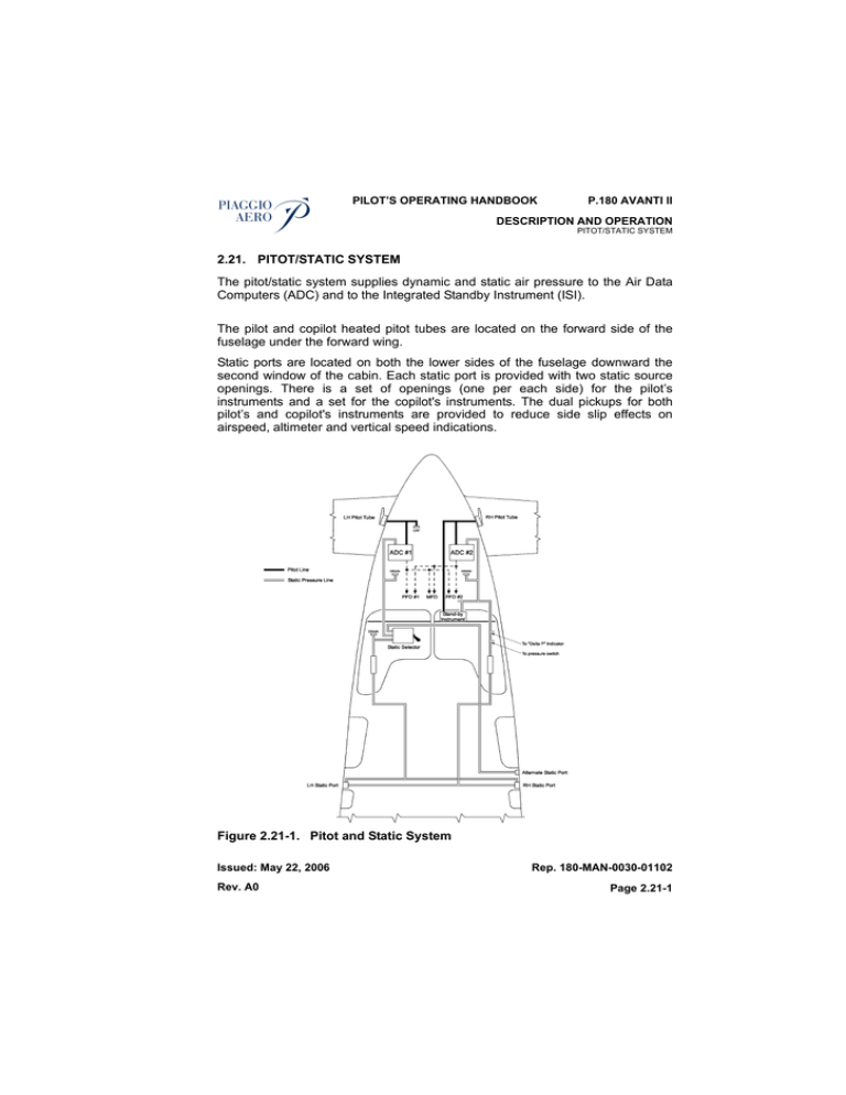
PILOT’S OPERATING HANDBOOK P.180 AVANTI II DESCRIPTION AND OPERATION PITOT/STATIC SYSTEM 2.21. PITOT/STATIC SYSTEM The pitot/static system supplies dynamic and static air pressure to the Air Data Computers (ADC) and to the Integrated Standby Instrument (ISI). The pilot and copilot heated pitot tubes are located on the forward side of the fuselage under the forward wing. Static ports are located on both the lower sides of the fuselage downward the second window of the cabin. Each static port is provided with two static source openings. There is a set of openings (one per each side) for the pilot’s instruments and a set for the copilot's instruments. The dual pickups for both pilot’s and copilot's instruments are provided to reduce side slip effects on airspeed, altimeter and vertical speed indications. Figure 2.21-1. Pitot and Static System Issued: May 22, 2006 Rev. A0 Rep. 180-MAN-0030-01102 Page 2.21-1 P.180 AVANTI II PILOT’S OPERATING HANDBOOK DESCRIPTION AND OPERATION PITOT/STATIC SYSTEM A screw plug drains is provided at the lowest point in the system on the fuselage belly under the cockpit. The anti-ice heating of the system is controlled through the PITOT/STATIC HTR switches, located in the ANTI-ICE panel on the central section of the instrument panel: – the left side pitot tube and static ports through the L & STALL switch, the power being supplied from the essential bus through the L PITOT ST HTR 10-ampere circuit breaker on the pilot circuit breaker panel; – the right side pitot tube and static ports through the R & TAT switch, the power being supplied from the right single feed bus through the R PITOT ST HTR 15-ampere circuit breaker on the copilot circuit breaker panel. The pitot heat indication system consists of a two amber caution lights on the annunciator display, marked L PITOT HTR and R PITOT HTR, and two current sensitive relays associated to each pitot heating system. The current sensitive relays, installed on the lines supplying power to the pitot heaters, monitor the current to the heating elements. The electrical power feeding the current sensitive relays is supplied through the stall warning circuit breaker, allowing the indication system operation also in the event of L/R PITOT ST HTR circuit breaker trip. Positive indication is provided whenever: – pitot heater is switched off, and – pitot heater is switched on but the heating elements absorbe less current than a minimum value expected under all operating conditions. During preflight tests the pilot can check the proper operation of the system by switching on then off the pitot heating systems. Pitot covers are provided with each pitot head and should be installed when the airplane is parked to prevent bugs and rain from entering the pitot head. A partially or completely blocked pitot system will give erratic or zero reading on the airspeed indicator. NOTE Before every flight, check to make sure the pitot covers have been removed and the static holes are unobstructed. Rep. 180-MAN-0030-01102 Page 2.21-2 Issued: May 22, 2006 Rev. A0 PILOT’S OPERATING HANDBOOK P.180 AVANTI II DESCRIPTION AND OPERATION PITOT/STATIC SYSTEM 2.21.1 ALTERNATE STATIC AIR SOURCE SYSTEM In addition to the normal static air source system an alternate static air line is provided. The alternate system consists of a selector valve connected to the left normal static air line and to analternate line that obtains static air from a heated static port located on the fuselage close the main right static port. In the event of a failure of the left normal static air source, the alternate source should be selected by lifting the spring-clip retainer of the STATIC PRESSURE SELECTOR VALVE handle, located in front of the control column just below the instrument panel, and moving the handle to the ALTERNATE SOURCE position. This will disconnect the normal static air line and connect the alternate static air line to the left side ADC (ADC1). The alternate static port heater is switched on when the right pitot static heater switch is set to the R position. 28 VDC power is supplied through the R PITOT ST HTR circuit breaker. NOTE The airspeed calibration change when the alternate static air source is in use. Refer to the PERFORMANCE Section of the Airplane Flight Manual for operation when the alternate static air source is in use. When the alternate static air source is not needed, ensure that the STATIC PRESSURE SELECTOR VALVE handle is held in the normal (STATIC TUBE) position by the spring-clip retainer. Issued: May 22, 2006 Rev. A0 Rep. 180-MAN-0030-01102 Page 2.21-3 PILOT’S OPERATING HANDBOOK P.180 AVANTI II DESCRIPTION AND OPERATION STALL WARN NG AND ANGLE OF ATTACK SYSTEM 2.22. STALL WARNING AND ANGLE OF ATTACK SYSTEM The stall warning and angle of attack system consists of an angle of attack transducer with internal heating for ice protection, a stall warning computer and two lighted STALL indications on the instrument panel. The angle of attack transducer is an electro-mechanical device which protrudes into the airflow on the right side of the fuselage between the third and the fourth window. By sensing the direction of the airflow the angle of attack transducer generates an electrical signal proportional to the angle of attack which is provided to the stall warning computer. The stall warning computer conditions the signals provided by the angle of attack transducer and drives the Low Speed Cue (LSC) indications on the Aispeed Tape of both the PFDs. The Low Speed Cues provide an approximation of stall speed, but do not serve as a stall warning system substitute. If the angle of attack signal is not valid (fail, missing, or not computed) a red boxed AOA flag shall be displayed in the PFD message window to the left of the Airspeed Tape. In addition the stall warning computer is connected with the flap system electronic control unit in order to change the stall threshold as a function of the flaps deployement. In the event of a malfunction the system will reset to the more conservative stall threshold condition with the flaps in completely retracted position. As well as a prestall condition is detected the stall warning computer causes the STALL red warning indications to illuminate, the aural warning box to emit a warning tone and, simultaneously, the autopilot to disengage if previously engaged. A STALL FAIL amber caution light on the annunciator display will illuminate in the event of failure either of the stall warning system or of the heating element in the angle of attack transducer. Two squat switches, one on the nose and the other one on the left landing gear leg, disengage the stall warning system when the airplane is on the ground. The correct operation of the stall warning system can be checked during the preflight check by means of the SYS TEST selector. Refer to the "System Test" paragraph of this Section for information about the test procedure and description. Anti-ice electrical heating of angle of attack transducer is controlled through the PITOT/STATIC HTR L & STALL-OFF switch located in the ANTI-ICE panel on the pilot instrument central subpanel. Issued: May 22, 2006 Rev. A0 Rep. 180-MAN-0030-01102 Page 2.22-1 P.180 AVANTI II PILOT’S OPERATING HANDBOOK DESCRIPTION AND OPERATION STALL WARNING AND ANGLE OF ATTACK SYSTEM The system is powered from the essential bus through the STALL WRN 3ampere circuit breaker on the pilot circuit breaker panel. Electrical power for heating of the angle of attack transducer is delivered from the left dual feed bus through the AOA HTR 10-ampere circuit breaker on the pilot circuit breaker panel. Rep. 180-MAN-0030-01102 Page 2.22-2 Issued: May 22, 2006 Rev. A0


