magnetic oil level indicator for power
advertisement
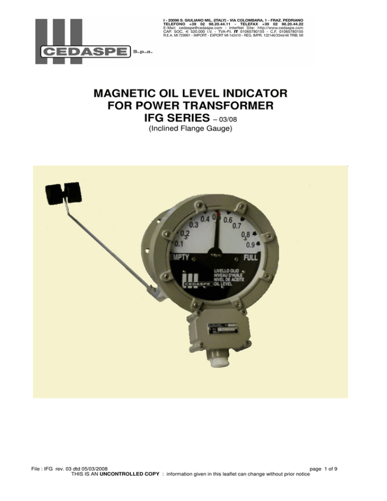
MAGNETIC OIL LEVEL INDICATOR FOR POWER TRANSFORMER IFG SERIES – 03/08 (Inclined Flange Gauge) File : IFG rev. 03 dtd 05/03/2008 page 1 of 9 THIS IS AN UNCONTROLLED COPY : information given in this leaflet can change without prior notice 1.0 Features The magnetic oil level indicators type IFG has been specially studied for use on power transformer to give an analogical indication of the oil level inside the conservator by a graduated dial with arrow plus one or more electric signal (max 4 signals) when the oil inside the conservator reaches the max or min level. 2.0 Construction features o Materials and components The body of the gauge is made in one piece of solid compact aluminium alloy casting oiltightned proof. The dial face is inclined of 20° from the connecting flange towards the ground, offering a better view at human height of the oil level indication system. The indicating system is located Inside the body and is composed by a yellow arrow, a graduated scale with ten division, one or more contacts activated by cams and a permanent magnet. The monitoring system is partially located inside the fixing flange and is composed by a permanent magnet, a bevel gear rigidly connected to a float arm which follows the movement of the surface of the oil. The two systems are connected by a magnetic joint obtained using the magnetic flux of the permanent magnets The electric signal coming from contacts are carried out through a waterproof terminal box (IP55) fitted with a PG16 cable gland and a ground screw o Oil-tightness and resistance to pressure The magnetic oil level indicators IFG are suitable to work with oil up to a max temperature of 115°C; lowest ambient temperature –25°C and are mechanically resistant to vacuum (10 torr) o Resistance to dynamical stress The magnetic oil level indicators IFG can operate without undue operation in following conditions: Sinus vibrations with frequency ≤120 Hz and amplitude ≤250 µm; Dynamical conditions causing following accelerations: - Max 3g in all directions, sinus vibration, amplitude ≤ 20 mm; - Shock condition with max 10 g in all directions. o Surface protection Body, frame, terminal box and cover are painted internally and externally with one primer coat of epoxy paint and externally with a finishing coat of polyurethane paint colour RAL 7030. The primer coat on the internal surfaces is compatible with transformer mineral oil up to temperatures of 120°C. Total thickness of two coats is 80 microns; special painting cycle can be provided for transformers located in very polluted areas 3.0 Manufacturing program Magnetic oil level indicator series IFG is manufactured in 2 different execution - Type IFG FK2 axial type suitable for use in conservator with rubber bag - Type IFG BQ2 radial type suitable for use on OLTC compartment All execution are equipped with 1,2 or more electric contacts , microswich type that are activated when the oil (and consequently the arrow of the instrument) reaches presetted positions. Indicating arrow moves over a 180° angle, float arm moves over an angle of 60°/140° respectively for type FK2, BQ2; for type BQ2 is also available a special execution with float arm rotation angle of 90°. White indicating dial having 10 divisions with black marking. 4.0 Operation, installation and maintenance o Operation Should an increase of oil inside the conservator (due to heating) or a decrease of oil (due to an oil loss) the float arm detects this variation and gives an optical signal (analogic type) through the arrow and when the oil reaches the presetted value for alarm and/or trip a microswitch is activated and an electric signal is provided inside the terminal box. o Installation Use one magnetic oil level indicator for the conservator of the main tank and one for OLTC conservator (if present); the oil level indicator can be fixed to the conservator using 8 (or 6) nuts M10 complete with washer and spring washer that have to be mounted on studs M10x30mm o Maintenance Magnetic oil level gauges IFG don’t need specific maintenance; we suggest to check regularly contacts during the normal maintenance of the transformer File : IFG rev. 03 dtd 05/03/2008 page 2 of 9 THIS IS AN UNCONTROLLED COPY : information given in this leaflet can change without prior notice 5.0 Electric contacts The contacts are microswitches changeover type and are mechanically operated by a cam. Following main characteristic of microswitches Lever Stainless steel Body and pushbutton Thermosetting composition Contact material Silver 7 Mechanical endurance of contact 1x10 cyles Temperature range -40°C - +125°C Standard interruption power AC AC 250V-5A Standard interruption power DC see diagram at end of brochure Insulation to earth at 20°C 2.000V Protection degree of terminal box IP 55 6.0 Wiring diagrams Available wiring diagram are: - wiring diagram type C1 : gives a signal when oil reaches low level inside conservator - wiring diagram type C2 : gives a signal when oil reaches low and max level inside conservator - wiring diagram type D1 : gives an alarm signal when oil reaches low level and trip signal for very low level inside conservator - wiring diagram type D2 : gives a double signal when oil reaches low level inside conservator All contacts are operated 3/5 degrees before the arrow reach the minimum or the maximum level of oil See sketch 7.0 Compatibility of installation The installation compatibility of the magnetic oil level indicator depend mainly on the material used for the flange gasket; therefore the executions differ because of the material used for this gasket. o Standard execution N – nitrile rubber gasket Admitted operating conditions are: Environmental conditions: Ambient temperature -25°C to +50°C Relative humidity 95% to 20°C - 80% to 40°C - 50% to 50°C Insulating liquid: transformer mineral or silicon oil Temperature - 25°C to + 115°C o Execution C – cork gasket Admitted operating conditions are: Environmental conditions: Ambient temperature -20°C to +50°C Relative humidity 95% to 20°C - 80% to 40°C - 50% to 50°C Insulating liquid: transformer mineral or silicon oil Temperature - 20°C to + 110°C o Special executions For other environmental and/or operating conditions to be examined individually. 8.0 Ordering Instructions When ordering must be defined following data: - Type of magnetic oil level indicator : IFG FK2 or BQ2 - Type of gasket required : N; C or special - Wiring diagram: C1; C2; D1; D2 - For type FK2 also float arm length or a mounting sketch showing min, max and filling levels of oil, (see form at the end of brochure) File : IFG rev. 03 dtd 05/03/2008 page 3 of 9 THIS IS AN UNCONTROLLED COPY : information given in this leaflet can change without prior notice File : IFG page 6 rev. 03 dtd 05/03/2008 page 6 of 9 THIS IS AN UNCONTROLLED COPY : information given in this leaflet can change without prior notice File : IFG page 8 rev. 03 dtd 05/03/2008 page 8 of 9 THIS IS AN UNCONTROLLED COPY : information given in this leaflet can change without prior notice MAGNETIC OIL LEVEL INDICATOR FOR POWER TRANSFORMER IMLO SERIES File : IMLO UNCONTROLLED COPY Rev. 3 dtd 10/10/08 1.0 FEATURES The gauges type IMLO, for oil immersed power transformers, give an analogic indication of the oil level inside the conservator on which are usually mounted; when required, they give an electric alarm signal if the oil reaches the minimum and/or the maximum admitted level. The body of the gauge, one piece only, is made of a solid casting of aluminium alloy; inside there is an indicating disc; in the front there is a dial made in transparent plexiglas with the marking of the maximum and minimum level and of the intermediate levels that the oil reaches at the temperature of -20°C, +20°C and +85°C (dial with different marking can be supplied upon request) The indicating disc is half white and half red coloured: at the minimum level you can see only the red part, at the maximum only the white part; at the intermediate levels, the red part of the disc which is visible is directly proportional to the oil level inside the conservator. The body has two hollow spaces containing the monitoring and the indication mechanism; a wall between the two hollow spaces guarantees a full separation between the oil inside the conservator and the ambient air. The magnetic oil level gauges consist of two mechanisms ("Monitoring" the first, "Indication" the second) connected between them by means of a magnetic joint. 1.1 Monitoring system One float fitted at one end of the arm follows the movement of the surface of the oil; the other end of the arm transmits the movement of the float to a magnet. The float may move on to a plan parallel to the dial (style R, page 5.27), or orthogonal (type IMLO Y 345 AMOSEAL page 5.29.F): in the first way the float arm is rigidly connected to the magnet; in the second, two bevel gears are in between the float-arm and the magnet. 1.2 Indication system It consists of one magnet and one indicating disc, one or more cams and as many contacts (depending on the wiring diagram) rigidly connected. The magnet of the monitoring system leads the magnet of the indication system during its movement, because of the magnetic flux. The indication system contains inside the min and/or max level switches and wiring. 2.0 MANUFACTURING PROGRAM 2.1 Radial type IMLO R 100-140-220-345, page 5.27 It is a complete family of oil level gauges, with four different body sizes, which make them suitable to be used either on small either on large power transformers; the choice of the size is function of the size of the conservator. They are normally fitted with changeover microswitches for minimum or for minimum and maximum level, so they can be used also on transformers subject to strong vibrations or in case of aseismic requirements. 2.2 Axial type IMLO-Y-345-ATMOSEAL page 5.29.F-G This oil level gauge is suitable for use on conservators with hermetically sealed rubber bag and it is normally fitted with one contact to operate at min oil level, but this doesn't exclude the possibility to use any other wiring diagrams. The page 5.29.G shows the two most common ways of mounting on the conservator end, vertical or with a slight inclination (fig B), or inclined at 45° under the conservator (fig A):a copy of this page filled with all the data can be used as an order form sheet. The possibility to choose among three executions (see page 5.29.F) that are different owing to the bevel gear ratio (ratio 1:2; ratio 1:3; ratio 1:4) offer a wide flexibility of use; the mounting of the bevel gear inside the body and an adjustablelength strong arm with two big rolling floats offer an high reliability. The dial of these gauges is customised with special marking for each job. 3.0 ELECTRIC SWITCHES CHARACTERISTICS 3.1 Rated current of the microswitches a.c.: 3 A (50 Hz) cosfi >0,4 at 250 V d.c.: 1 A at 30V / 0,27 A at 110 V / 0,13 A at 220 V Breakdown voltage between contacts: 750 V Operating life: 30.000.000 cycles at 1 Hz 3.2 Precision of the indication: +1°/-5° disc rotation. (L/R=5 ms) 4.0 CONTACT DESIGN & SYMBOLS 4.1 Only changeover contacts are available. (the switch changes-over the circuit at the set point) File : IMLO UNCONTROLLED COPY Rev. 3 dtd 10/10/08 4.2 Symbols of contacts F: min changeover contacts G: max changeover contact 4.3 Wiring diagrams -Styles available for all sizes FM : 1 electric contact at Min level FGM : 1 electric contact at Min level and 1 electric contact at Max level -Styles available for the sizes 140,220,345 FFM – S : 2 electric contact at Min level operating simultaneously FFM – A : 2 electric contacts operating sequentially at Min level (alarm and trip wiring diagram) -Styles available for the sizes 220 & 345 FFGGM : 2 electric contact at Min level and 2 electric contacts operating at Max level See page 5.29D for the sketches of the wiring diagram and the identification of the terminals 5.0 CABLE BOX Our gauges are fitted with a weatherproof cable box, with a PG16 cable gland and a ground screw. 6.0 OPERATING TEMPERATURE Our oil level gauges are manufactured in order to withstand oil temperature between -25°C and +100°C and ambient temperature between -25°C and +85°C. 7.0 SWITCHES SET-POINT The set point of the switches is calibrated 2° to 5° in advance to the min or max level. Overlap at min or max level: 5° (angular) Switching differential: 5° 8.0 GROUND INSULATION TEST Each gauge is tested at 2000 V a.c. (50 Hz) for 60", between the gauge housing and the electric circuits, and between the two indipendent circuits. 9.0 PROTECTION DEGREE: IP 55 10.0 EXTERNAL SURFACES FINISH: epoxy paint RAL 7030, Stainless steel screws. 11.0 SPECIAL REQUIREMENTS - Special dial marking - Cable gland adaptor PG16 to 3/4" or M20x1;5 or 1"W - Special executions for desert or for highly polluted atmosphere 12.0 MOUNTING INSTRUCTIONS Normally the " Y " execution is suggested when it is necessary to mount an oil level gauge on the cylindrical surface of the conservator; the " R " execution, the most commonly used, is suitable for mounting on the front or back ends of the conservator. Welding studs or blind tapped holes are both acceptable ways to fix the gauge on the wall, using respectively nuts or screws(see page 5.29.D for mounting sketch); a flat cork impregnated gasket, supplied together with the gauge, must be put between gauge and wall before tightening; on demand sizes 140 and 220 may be supplied with an O/ring tightening flange gasket. At page 5.27 you find the formula for the calculation of the arm float length ”R” and of the distance “S” between centre of the dial and of the conservator. 13.0 ORDER INSTRUCTIONS The following details must be given when issuing an order, or asking a quotation: - Type - Float movement design - Size - Wiring diagram EXAMPLE IMLO R 220 FG M | | | | Wiring diagram | | | Gauge size | | Float movement style | Type For type IMLO Y 345 ATMOSEAL should be also defined dimension stated at page 5.29.G File : IMLO UNCONTROLLED COPY Rev. 3 dtd 10/10/08 MAGNETIC OIL LEVEL INDICATOR FOR POWER TRANSFORMER NFG SERIES (Normal Front Gauge Mounting Series 2009) File : NFG rev. 07 data 07/10/2009 page 1 of 10 IMPORTANT NOTICE : This is an uncontrolled copy . Information given in this leaflet can change without prior notice 1.0 Features The magnetic oil level indicators type NFG has been specially studied for use on power transformer to give an analogical indication of the oil level inside the conservator by a graduated dial with arrow plus one or more electric signal (max 4 signals) when the oil inside the conservator reaches the max or min level. 2.0 Construction features Materials and components The body of the gauge is made in one piece of solid compact aluminium alloy casting oil tightened proof. The indicating system is located Inside the body and is composed by a yellow arrow, a graduated scale, one or more contacts activated by cams and a permanent magnet. The monitoring system is located behind the fixing flange (it is fully inside the conservator, this in order to minimize the external protrusion of the gauge itself from the conservator tank) and is composed by a permanent magnet, rigidly connected (or by means of a bevel gear for form Y) to a float arm which follows the movement of the surface of the oil. The two systems are connected by a magnetic joint through the magnetic flux of the permanent magnets. The electric signal coming from the contacts are carried out through a waterproof terminal box (IP55) with a M25x1.5 threaded entry (see page NFG5). Upon request we can supply adaptors M25x1.5 to M20x1.5 or to PG16. Also upon request we can supply cable glands M25x1.5 or M20x1.5 or PG16. Oil-tightness and resistance to pressure The magnetic oil level indicators NFG are leak tested (routine test) and are mechanically resistant to vacuum (10 torr). Resistance to dynamical stress The magnetic oil level indicators NFG can operate without undue operation in following conditions: Sinus vibrations with frequency ≤120 Hz and amplitude ≤250 µm; Dynamical conditions causing following accelerations: - Max 3g in all directions, sinus vibration, amplitude ≤ 20 mm; - Shock condition with max 10 g in all directions. Surface protection Body, frame, terminal box and his cover are painted internally and externally with one primer coat of epoxy paint and externally with a finishing coat of polyurethane paint colour RAL 7030. The primer coat on the internal surfaces is compatible with transformer mineral oil up to temperatures of 120°C. Total thickness of two coats is 80 microns; upon request we can supply gauges with special painting for transformers located in very polluted areas. 3.0 Manufacturing program Magnetic oil level indicator series NFG is manufactured in 3 sizes with 2 different styles: Size 1: flange OD 140mm; Dial ND 100mm (4 inches); Size 2: flange OD 220mm; Dial ND 150mm (6 inches); Size 3: flange OD 345mm; Dial ND 250mm (10 inches); Style Y: axial float arm suitable for use on traditional breathing conservator and on hermetic conservator with rubber bag - Style R: radial float arm suitable for use on traditional breathing conservator. All execution are fitted with 1 or more electric contacts, microswitch type, that are activated when the oil (and consequently the arrow of the instrument) reaches the presetted positions (see available wiring diagram). The indicating arrow in type “R” moves over a 140° angle, the float arm moves over an angle of 140°. The indicating arrow in type “Y” moves over a 140° angle, the float arm moves over an angle of 60°. The gauge type “Y” has a special design that allow the mounting of the same gauge either in the centre of the conservator end, or the bottom of the conservator end, or inclined below the conservator, just fixing the float arm in a specific way without any special adjustment (see sketch page NFG6) The standard Indicating dial has 10 divisions with yellow figures other dials are available (see page NFG6). - File : NFG rev. 07 data 07/10/2009 page 2 of 10 IMPORTANT NOTICE : This is an uncontrolled copy . Information given in this leaflet can change without prior notice 4.0 Operation, installation and maintenance Operation The float arm detects an increase (due to heating) or a decrease (due to an oil loss) of oil inside the conservator, giving a visible indication (analogical type) through the arrow and when the oil reaches the presetted value for alarm and/or trip a microswitch is activated and an electric signal is provided inside the terminal box. Installation Use one magnetic oil level indicator for the conservator of the main tank and one for OLTC conservator (if present); the oil level indicator can be fixed to the conservator using studs & nuts (type B) or screws (type V) M6 (6 pcs) or M10 (8 pcs) with washer and spring washer (see the page NFG5). Adjusting float arm length NFG form Y are supplied with adjustable float arm length; this in order to have an optimal calibration of the instrument. Adjustment is very easy: you need only to unloose screw A (please refer to page NFG5), adjust float arm to desired length and close screw A again. Maintenance Magnetic oil level gauges NFG don’t need specific maintenance; we suggest to check regularly contacts during the normal maintenance of the transformer. 5.0 Electric contacts The contacts are microswitches changeover type and are mechanically operated by a cam. Following main characteristic of micro switches: Lever Stainless steel Body and pushbutton Thermosetting composition Contact material Silver 7 Mechanical endurance of contact 1x10 cycles Temperature range -40°C - +125°C Standard interruption power AC AC 250V-5A Standard interruption power DC see diagram at page NFG5 Insulation to earth at 20°C 2.000V Protection degree of terminal box IP 55 6.0 Wiring diagrams Available wiring diagram are (see page NFG5): wiring diagram type C1 : gives a signal when oil reaches low level inside conservator wiring diagram type C2 : gives a signal when oil reaches low or max level inside conservator wiring diagram type D1 : gives an alarm signal when oil reaches low level and trip signal for very low level inside conservator - wiring diagram type D2 : gives a double signal when oil reaches low level inside conservator - wiring diagram type D4 : gives a double signal when oil reaches low or max level inside conservator All contacts are operated 3/5 degrees before the arrow reaches the minimum or the maximum level of oil. - 7.0 Compatibility of installation The installation compatibility of the magnetic oil level indicator depend mainly on the climatic conditions related to ambient temperature and oil temperature (that influence choice of the material used for the flange gasket) and on environmental conditions (that influence choice of the material used for front dial and fittings) ; therefore the executions differ because of the different materials used for gaskets; front dial and fittings. Execution related to climatic conditions: N – O/RING made in HNBR (hydrogenated nitrile rubber) This is standard execution on sizes 1 & 2 Admitted operating conditions are: Environmental conditions: Ambient temperature: -40°C to +55°C Relative humidity: 95% to 20°C - 80% to 40°C - 50% to 50°C Insulating liquid (transformer mineral oil): Temperature: - 40°C to + 140°C File : NFG rev. 07 data 07/10/2009 page 3 of 10 IMPORTANT NOTICE : This is an uncontrolled copy . Information given in this leaflet can change without prior notice C – NBC Cork gasket (flat flange gasket with 6 or 8 holes instead of O-Ring gasket) This is standard execution on size 3 and on demand on sizes 1 & 2 Admitted operating conditions are: Environmental conditions: Ambient temperature: -20°C to +50°C Relative humidity: 95% to 20°C - 80% to 40°C - 50% to 50°C Insulating liquid (transformer mineral or silicon oil): Temperature: - 20°C to + 110°C G – LT Cork gasket (flat flange gasket with 6 or 8 holes instead of O-Ring gasket) This execution is on demand on all sizes for low temperature applications Admitted operating conditions are: Environmental conditions: Ambient temperature: -55°C to +50°C Relative humidity: 95% to 20°C - 80% to 40°C - 50% to 50°C Insulating liquid (transformer mineral or silicon oil): Temperature: - 55°C to + 160°C Execution related to environmental conditions: 0 – For normal and tropical conditions Front dial made in P.M.M.A.; fittings made in brass nickel plated and s/steel AISI 304 7 – For desert conditions and / or moderated corrosive conditions Front dial made in tempered glass; fittings made in brass nickel plated and s/steel AISI 304 8 – For extremely corrosive conditions Front dial made in tempered glass; fittings made in brass nickel plated and s/steel AISI 316 Special executions For other environmental and/or operating conditions to be examined individually. 8.0 Ordering Instructions When ordering must be defined following data (see order form at page 10 of catalogue): - Style of magnetic oil level indicator : R or Y - Size 1 (flange OD 140 mm); 2 (flange OD 220 mm); or 3 (flange OD 345 mm) - Mounting sketch (for R style always A); - Wiring diagram: C1; C2; D1; D2; D4; - Climatic conditions (type of gasket: N; C; G or special); - Environmental conditions (0; 7; 8 or special); - Type of dial : 0; 1; 5; or special; - Special requirement i.e. Cable Entry. Example : to order 5 magnetic oil level indicator type NFG form Y, OD 220mm, mounting on traditional conservator, 2 contacts SPDT at min and max level, with HNBR gaskets, normal environmental conditions and dial marking Min, -20, 20, 85, Max, write: - Nr. 5 Magnetic oil level indicator NFG Y2AC2N00. 9.0 Marking on data plate All our magnetic oil level indicator have a data plate with S/N and model of the instrument Example : on above oil level gauge type NFG form Y, OD 220mm, mounting on traditional conservator, 2 contacts SPDT at min and max level, with HNBR gaskets, normal environmental conditions and dial marking Min, -20, 20, 85, Max, will have the following marking engraved on field Type: Y2AC2N00. File : NFG rev. 07 data 07/10/2009 page 4 of 10 IMPORTANT NOTICE : This is an uncontrolled copy . Information given in this leaflet can change without prior notice PAGE NFG10 ORDER FORM R Y RADIAL AXIAL FLANGE DIA 140 MM FLANGE DIA 220 MM FLANGE DIA 345 MM MOUNTING SKETCH A 1 2 3 A (TRADITIONAL CONSERVATOR STANDARD FOR TYPE "R") MOUNTING SKETCH "B" ON FRONT OF CONSERVATOR WITH RUBBER BAG AND CONVENTIONAL TAU1:2 B (FLOAT ACC DRG 5607 & ROTATION 60°) H MOUNTING SKETCH "H" ON FRONT OF CONSERVATOR WITH RUBBER BAG AND TAU1:4 C MOUNTING SKETCH "C" BELOW CONSERVATOR WITH RUBBER BAG AND CONVENTIONAL TAU1:2 K MOUNTING SKETCH "K" BELOW CONSERVATOR WITH RUBBER BAG AND TAU1:4 (FLOAT ACC DRG 5607 & ROTATION 35°) (FLOAT ACC DRG 5607 W/ARM ADAPTOR DRG 2735 & ROTATION 60°) (FLOAT ACC DRG 5607 W/ARM ADAPTOR DRG 2735 & ROTATION 35°) C1 C2 D1 D2 D4 0 1 MIN CONTACT 1 MIN + 1 MAX CONTACTS 2 MIN CONTACTS, ALARM + TRIP 2 MIN CONTACTS SIMULTANEOUS 2MIN + 2MAX CONTACTS SIMULTANEOUS HNBR GASKETS (AMBIENT TEMPERATURE -40/55 °C) NBC CORK GASKETS (AMBIENT TEMPERATURE -20/50°C) LT CORK GASKETS (AMBIENT TEMPERATURE -55/50°C) SPECIAL GASKETS STANDARD & TROPICAL 7 DESERT AND / OR MODERATED CORROSIVE 8 EXTREMELY CORROSIVE N C G S (DIAL MADE IN P.M.M.A. AND SCREWS MADE IN AISI 304) (DIAL MADE IN TEMPERED GLASS AND SCREWS MADE IN AISI 304) (DIAL MADE IN TEMPERED GLASS AND SCREWS MADE IN AISI 316) 9 0 1 5 9 N 0 0 DIAL MARKING 1 ENVIRONMENTA L CONDITIONS C CLIMATIC CONDITIONS A WIRING DIAGRAM 1 MOUNTING SKETCH LEGENDA SIZE STYLE AN AN R SPECIAL MIN/-20°C/20°C/85°C/MAX MIN/1;2;…8;9;10/MAX MIN / 25°C/ MAX SPECIAL EXAMPLE MARKING ON DATA PLATE CEDASPE CODE NOTE ON CABLE ENTRY : OIL LEVEL INDICATOR IS SUPPLIED WITH CABLE ENTRY M25X1.5 AND ADAPTOR TO M20x1,5. DIFFERENT CABLE ENTRIES AND CABLE GLAND ARE AVALAIBLE ON DEMAND (SEE PAGE 5 OF CATALOGUE) SPECIAL REQUIREMENTS / NOTE / OPTIONALS ……………………………………………...................................................................…...................…………………………………… …………............................................………………………………………………………………………………………………………… ……………………………………......................................................................................................................................................... .......................................................................................................................................................................................... REV. 06 DTD 30/03/2009
