Chapter 2 The Production and Properties of X Rays X
advertisement

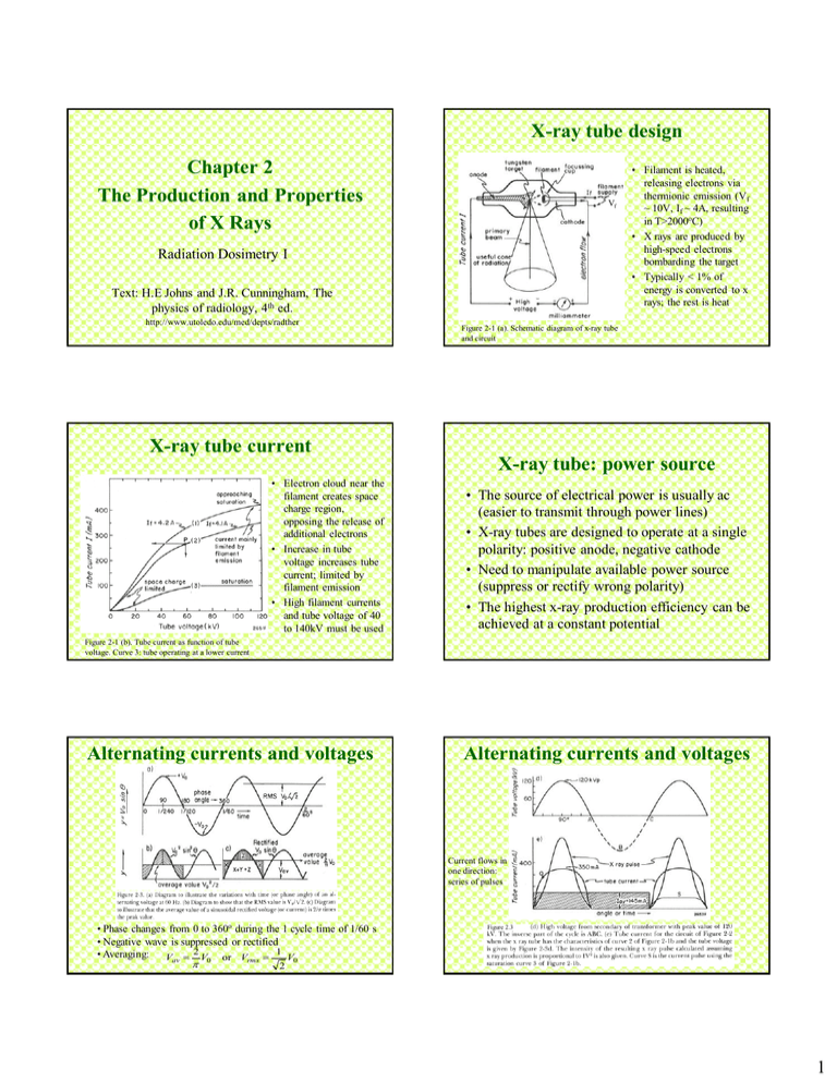
X-ray tube design Chapter 2 The Production and Properties of X Rays Vf Radiation Dosimetry I Text: H.E Johns and J.R. Cunningham, The physics of radiology, 4th ed. http://www.utoledo.edu/med/depts/radther • Filament is heated, releasing electrons via thermionic emission (Vf ~ 10V, If ~ 4A, resulting in T>2000oC) • X rays are produced by high-speed electrons bombarding the target • Typically < 1% of energy is converted to x rays; the rest is heat Figure 2-1 (a). Schematic diagram of x-ray tube and circuit X-ray tube current X-ray tube: power source • Electron cloud near the filament creates space charge region, opposing the release of additional electrons • Increase in tube voltage increases tube current; limited by filament emission • High filament currents and tube voltage of 40 to 140kV must be used • The source of electrical power is usually ac (easier to transmit through power lines) • X-ray tubes are designed to operate at a single polarity: positive anode, negative cathode • Need to manipulate available power source (suppress or rectify wrong polarity) • The highest x-ray production efficiency can be achieved at a constant potential Figure 2-1 (b). Tube current as function of tube voltage. Curve 3: tube operating at a lower current Alternating currents and voltages Alternating currents and voltages Current flows in one direction: series of pulses • Phase changes from 0 to 360o during the 1 cycle time of 1/60 s • Negative wave is suppressed or rectified 2 1 • Averaging: Vav V0 or Vrms V0 2 Figure 2.3 1 Three phase units Rectification • Need to increase pulse repetition rate to deliver high x ray flux in a short period of time • Three phase units: voltage between any pair of 3 wires Tube potential is almost constant, with a “ripple” Example 1 • Which type of x-ray generator produces the highest effective tube voltage, assuming the peak voltage is applied across the tube? Example 2 Ratio of the turns in a transformer is N. Given an input RMS (primary) voltage, what is the peak output (secondary) voltage? Faraday’s law: VS N S A. One-phase B. Three-phase C. Constant potential D. The effective voltage is the same for all types above. In C - effective voltage = peak voltage d ; dt VP N P d dt VS N S N VP N P VS N 2 VP RMS VRMS V0 / 2 Diagnostic x ray tubes Example 3 • What energy (kJ) is imparted to a rotating anode (0.25 kg) during a 2 s exposure that produced a temperature of 2500oC. Specific heat of tungsten is 0.035 kcal/kgoC, and 1 cal = 4.186 J A. B. C. D. E. • The objective is to deliver x ray beam from a point source in a very short time • To overcome heating need to spread electrons over some area that appears as a point 17.9 45.7 87.5 91.5 182.9 Duration of exposure is irrelevant E cmT 0.035 4.186 103 0.25 2500 91.5 103 91.5 kJ 2 Diagnostic x ray tubes Image from http://www.slideshare.net/jdtomines/x-ray-tube • X-rays that are emitted from the target travel through different thickness of cathode material • Heel effect: radiation intensity toward the cathode side of the xray tube is higher than on the anode side • Cathode is typically mounted over the thicker part of the patient to balance the amount of transmitted photons on the imager Rating of diagnostic tubes • Focal spot loading determines the maximum permissible exposure: there is a maximum power that can be tolerated before target starts melting (Tmelting=3400oC for tungsten) • Anode cooling and housing cooling rates determine the number of exposures that may be given in a sequence Intensity profile Rating of diagnostic tubes • The combination of current and voltage must lie to the left of the appropriate curve • The maximum duration of a single exposure depends on spot size, anode rotation speed, current, voltage, power supply type X ray tubes for radiotherapy Rating of diagnostic tubes • Heat stored in the anode and its cooling rate limits the number of exposures given in a sequence • Heat unit HU characterizes the energy deposited within the anode in a single exposure X-ray spectra • Mostly for superficial treatments • No need for a small spot source • The instantaneous energy input is small (about 1/10) but the average energy input is ~ 10 times greater compared with a diagnostic tube • Due to much higher energy (>200keV) of electrons bombarding the target, there is a problem of secondary electrons emerging from the target – Solution: the target is placed in a “hood” - hollow tube with copper shielding intercepting the secondary electrons 3 Interactions of electrons with the target to give x rays Characteristic radiation Most probable; no x-rays produced Breaking radiation • Different transitions have different probabilities, according to quantum mechanics selection rules (some transitions are forbidden) Bremsstrahlung interaction Thick target Thin target Example 4 • The energy levels of K, L, and M shells in tungsten are -69.5, -11.0, and -2.5 keV. What photon energies will be present in its characteristic X-ray spectrum? Photon energies are equal to the differences • Thin target approximation: one collision per electron • Thick target approximations: I(E) = C Z (Emax - E) Example 6 Example 5 • In the graph below, the two X-ray spectra shown have the same 1. Filtration 2. Target material 3. HVL 4. KVp A. 1,2,3,4 B. 1,3 C. 2,4 D. 3,4 E. 4 only A. 67.0, 58.5, 8.5 keV between corresponding energy levels B. 80.5, 72.0, 13.5 keV C. 69.5, 1 1 .O, 2.5 keV D. Continuous spectrum from 2.5 to 69.5 keV E. Continuous spectrum below 2.5 keV Same characteristic peaks = same target Same kVp • A target material has the following binding energies: K=30 keV, L=4 keV, M=0.7 keV. If 40.0 keV electrons are fired at the target, what kind of x-rays can have the following energies? • 6-1: 34 keV • 6-2: 26 keV • 6-3: 40.7 keV A. Characteristic only B. Bremsstrahlung only C. Both A and B D. Neither A nor B Answers: • 6-1: B • 6-2: C • 6-3: D Different intensity – different filtration and HVL 4


