Teledyne Relays AS24D6C Datasheet
advertisement
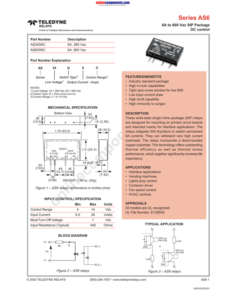
Series AS6 6A to 600 Vac SIP Package DC control Part Number Description AS24D6C 6A, 280 Vac AS60D6C 6A, 600 Vac Part Number Explanation FEATURES/BENEFITS • Industry standard package • High in-rush capabilities • Tight zero-cross window for low EMI • Low input current draw • High dv/dt capability • High immunity to surges co m NOTES 1) Line Voltage: 24 = 280 Vac; 60 = 600 Vac 2) Switch Type: D = Zero-cross turn-on 3) Control Range: C = 4–14 Vdc Bottom View s. MECHANICAL SPECIFICATION 1800A2s 1.0 (25.4) output 230 Vac 6A 2 1 om input 4-14 Vdc 4- 3+ po .39 (10.2) ne .10 (2.58) 1.70 (43.2) DESCRIPTION These solid-state single inline package (SIP) relays are designed for mounting on printed circuit boards and intended mainly for interface applications. The relays integrate 50A thyristors to switch permanent 6A currents. They can withstand very high current overloads. The relays incorporate a direct-bonded copper substrate. This technology offers outstanding thermal efficiency as well as thermal stress performance, which together significantly increase life expectancy. nt .30 (7.62) .39 (10.2) .19 (6.5) Ø1 .30 (7.63) .30 (7.62) ec .49 .40 (12.7) (10.16) .20 (5.08) lin WEIGHT: 1.06 oz. (30g) on Figure 1 – AS6 relays; dimensions in inches (mm) APPLICATIONS • Interface applications • Vending machines • Light/Lamp control • Contactor driver • Fan speed control • HVAC controls INPUT (CONTROL) SPECIFICATION Control Range Input Current Min Max Units 4 14 Vdc 6.5 30 mAdc 1 Vdc 440 Ohms Must Turn-Off Voltage Input Resistance (Typical) APPROVALS All models are UL recognized. UL File Number: E128555. TYPICAL APPLICATION L1 BLOCK DIAGRAM MOV on the PCB 3+ Rc Ic L1 1~ Load or SSR MOV on the PCB Vc Load 4– 2~ Figure 2 – AS6 relays © 2003 TELEDYNE RELAYS SSR N N Figure 3 – AS6 relays (800) 284-7007 • www.teledynerelays.com AS6 1 AS6\032003\Q1 Series AS6 OUTPUT (LOAD) SPECIFICATION ENVIRONMENTAL SPECIFICATION Min Max Unit Min Operating Temperature AS24D6C 12 280 Vrms Storage Temperature AS60D6C 24 600 Vrms Input-Output Isolation 4000 AS24D6C 600 VPeak AS60D6C 1200 VPeak Operating Range Max Unit –40 80 °C –40 120 °C Vrms Peak Voltage 8 Arms 7 Maximum Surge Current Rating (Non-Repetitive) 6 600 APeak On-State Voltage Drop 1.6 V Zero-Cross Window (Typical) 12 V Off-State Leakage Current (60Hz) 1 mA Turn-On Time (60Hz) 8.3 ms Turn-Off Time (60Hz) 8.3 ms 5 4 3 2 ne (See Figure 6) Load Current (A) (See Figure 5) co 6 s. .005 nt Load Current Range m LOAD CURRENT DERATING CURVE 1 500 V/µs 10 po 0 Off-State dv/dt (Non-Repetitive) Operating Frequency I2t for Match Fusing (<8.3ms) 440 10 20 50 60 70 80 90 100 A2S SURGE CURRENT ec 700 600 Non-Repetitive 500 Apeak lin on Input Current (mA) 40 Figure 5 – AS6 relays Hz CONTROL CHARACTERISTIC 30 28 26 24 22 20 18 16 14 12 10 8 6 4 2 0 30 Ambient Temperature (°C) om 1800 0 400 300 200 100 Repetitive with initial Tj = 70°C 0 0.01 0.1 1 t (s) 0 1 2 3 4 5 6 7 8 9 10 11 12 13 14 15 16 Control Voltage (V) Figure 4 – AS6 relays Long time overload @ Tj init = 45°C Time 60s 100s I (A) 20 15 Figure 6 — AS6 Relays NOTES: 1. External MOV recommended for inductive loads. 2. HS and LS Series relays available for higher current. 3. Electrical specifications at 25°C unless otherwise specified. 4. For 800Hz applications, contact factory. 5. For additional/custom options, contact factory. AS6 2 SPECIFICATIONS ARE SUBJECT TO CHANGE WITHOUT NOTICE © 2003 TELEDYNE RELAYS AS6\032003\Q1

