A Few Hints about soldering on a Ground Plane
advertisement

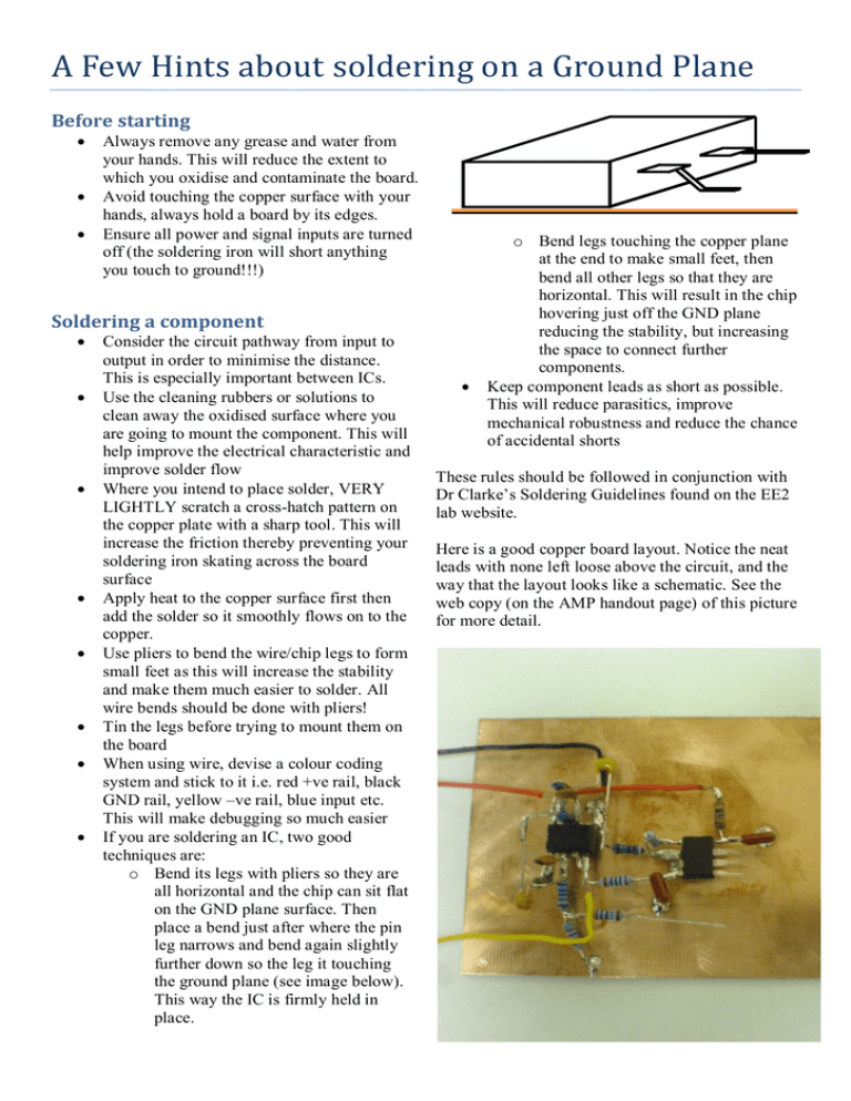
A Few Hints about soldering on a Ground Plane Before starting Always remove any grease and water from your hands. This will reduce the extent to which you oxidise and contaminate the board. Avoid touching the copper surface with your hands, always hold a board by its edges. Ensure all power and signal inputs are turned off (the soldering iron will short anything you touch to ground!!!) Soldering a component Consider the circuit pathway from input to output in order to minimise the distance. This is especially important between ICs. Use the cleaning rubbers or solutions to clean away the oxidised surface where you are going to mount the component. This will help improve the electrical characteristic and improve solder flow Where you intend to place solder, VERY LIGHTLY scratch a cross-hatch pattern on the copper plate with a sharp tool. This will increase the friction thereby preventing your soldering iron skating across the board surface Apply heat to the copper surface first then add the solder so it smoothly flows on to the copper. Use pliers to bend the wire/chip legs to form small feet as this will increase the stability and make them much easier to solder. All wire bends should be done with pliers! Tin the legs before trying to mount them on the board When using wire, devise a colour coding system and stick to it i.e. red +ve rail, black GND rail, yellow –ve rail, blue input etc. This will make debugging so much easier If you are soldering an IC, two good techniques are: o Bend its legs with pliers so they are all horizontal and the chip can sit flat on the GND plane surface. Then place a bend just after where the pin leg narrows and bend again slightly further down so the leg it touching the ground plane (see image below). This way the IC is firmly held in place. o Bend legs touching the copper plane at the end to make small feet, then bend all other legs so that they are horizontal. This will result in the chip hovering just off the GND plane reducing the stability, but increasing the space to connect further components. Keep component leads as short as possible. This will reduce parasitics, improve mechanical robustness and reduce the chance of accidental shorts These rules should be followed in conjunction with Dr Clarke’s Soldering Guidelines found on the EE2 lab website. Here is a good copper board layout. Notice the neat leads with none left loose above the circuit, and the way that the layout looks like a schematic. See the web copy (on the AMP handout page) of this picture for more detail.


