Step and Touch Potentials
advertisement

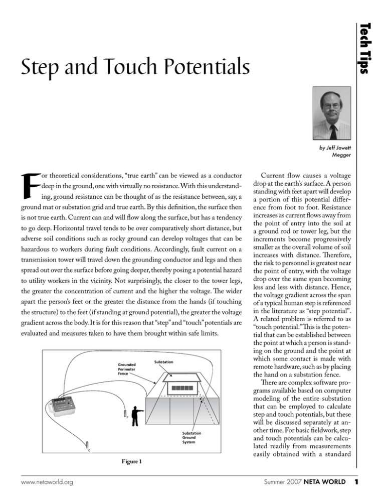
Tech Tips Step and Touch Potentials by Jeff Jowett Megger F or theoretical considerations, “true earth” can be viewed as a conductor deep in the ground, one with virtually no resistance. With this understanding, ground resistance can be thought of as the resistance between, say, a ground mat or substation grid and true earth. By this definition, the surface then is not true earth. Current can and will flow along the surface, but has a tendency to go deep. Horizontal travel tends to be over comparatively short distance, but adverse soil conditions such as rocky ground can develop voltages that can be hazardous to workers during fault conditions. Accordingly, fault current on a transmission tower will travel down the grounding conductor and legs and then spread out over the surface before going deeper, thereby posing a potential hazard to utility workers in the vicinity. Not surprisingly, the closer to the tower legs, the greater the concentration of current and the higher the voltage. The wider apart the person’s feet or the greater the distance from the hands (if touching the structure) to the feet (if standing at ground potential), the greater the voltage gradient across the body. It is for this reason that “step” and “touch” potentials are evaluated and measures taken to have them brought within safe limits. Grounded Perimeter Fence Substation E P Substation Ground System Figure 1 www.netaworld.org Current flow causes a voltage drop at the earth’s surface. A person standing with feet apart will develop a portion of this potential difference from foot to foot. Resistance increases as current flows away from the point of entry into the soil at a ground rod or tower leg, but the increments become progressively smaller as the overall volume of soil increases with distance. Therefore, the risk to personnel is greatest near the point of entry, with the voltage drop over the same span becoming less and less with distance. Hence, the voltage gradient across the span of a typical human step is referenced in the literature as “step potential”. A related problem is referred to as “touch potential.” This is the potential that can be established between the point at which a person is standing on the ground and the point at which some contact is made with remote hardware, such as by placing the hand on a substation fence. There are complex software programs available based on computer modeling of the entire substation that can be employed to calculate step and touch potentials, but these will be discussed separately at another time. For basic fieldwork, step and touch potentials can be calculated readily from measurements easily obtained with a standard Summer 2007 NETA WORLD four-terminal ground tester. One current lead from the tester is connected to the system ground at some convenient point of contact, and the other current lead is clipped to a probe driven into the ground at a convenient remote position outside the substation fence. One potential terminal is then connected by a lead to an appropriate position on the fence, and the second potential terminal is connected by a lead to a probe driven into the ground about three feet (the length of a typical adult human stride) outside the fence (Fig. 1). The tester is energized and a resistance measurement obtained. By employing Ohm’s law, V = IR and using the maximum fault current from the system design along with the measured resistance, the touch potential across a human body is calculated. For step potential, the connection to the fence is taken down and moved to a second probe driven into the soil about three feet from the other probe. The other three terminals remain connected as they were, and the tester is reenergized (Fig. 2). Again, the resistance reading from the tester is employed in Ohm’s law as shown above, and the step potential is calculated. These two values indicate the maximum voltage to which a person (utility worker or hapless passerby) could be subjected if touching a substation fence or walking close to it while a fault condition is occurring. These calculations typically yield about a 20 percent accuracy, with more rigorous techniques available, as mentioned above, where warranted. For worker safety, protective mats can be utilized. These can be either insulating or conducting mats. They produce the desired effect through opposite means. The former, of course, isolates the person by interrupting the circuit path, while the latter maintains constant potential over the worksite area. A conducting mat moves the problem area, with the voltage gradient now starting at the mat’s edge. Maximum step potential exists at the edge, so a nonconductive ladder may be laid on the ground to act as a safe approach. Substation yards are covered by coarse stone to increase protection by diverting fault current into the more conductive soil beneath. A grade of stone one inch or larger is used in order to provide air gaps that act as further insulation between stones. Otherwise the stone tends to pack tight and defeat the purpose. It also prevents the growth of vegetation, which presents a safety hazard in its own right. Substation grounding must dissipate normal and fault currents without exceeding operating or equipment limits or adversely affecting continuity of service in addition to assuring safety of workers and civilian personnel who happen to be walking in the vicinity. It was once assumed that any ground connection, however crude, made an object safe to touch. But there is no simple relationship between ground resistance of a system as a whole and maximum shock current to which a person might be subjected. Examples of this seeming conundrum can be illustrated accordingly. A substation supplied from an overhead line will experience NETA WORLD Summer 2007 Substation Grounded Perimeter Fence E A B Substation Ground System Figure 2 total ground fault current entry into the earth, causing a steep rise of local ground potential. Since current is entering via an aerial conductor and air is a good insulator, substantial fault current will travel on the grounding conductor and enter the earth at a defined point, thereby leading to high voltage gradients in the immediate vicinity. A low system ground resistance is therefore critical. Where an underground cable feeder is present, a major part of fault current returns through the enclosure or cable sheaths directly to the source, thereby establishing a low-resistance metallic link parallel to the earth return. This lessens the magnitude of ground potential rise. So in the one case, a danger to personnel might still exist despite the presence of what might otherwise be considered a low ground resistance, while in the other instance, a much higher ground resistance might still provide a safe environment. It can be seen, therefore, that the design of the overall system, not just that of the grounding grid itself, can contribute to a safe facility, even in what might otherwise be considered poor grounding soils. By extension, the ultimate design is one where the product of maximum short-circuit current and ground resistance represents a voltage low enough to be contacted safely. The number of factors that contribute to ground fault clearance and the complexity of their interrelationships indicate that a grounding system might not be adequate in terms of safety even while capable of sustaining fault current in magnitude and duration as permitted by protective relays. Safe grounding can be viewed as a balance between two parallel systems: the permanent one of buried electrode and the accidental one established by personnel contact in the vicinity. Critical factors, as indicated above, include: • relatively high fault current in relation to the size of ground system and its resistance • soil resistivity and the manner in which it affects distribution of ground current flow • the coincidence of the presence of an individual at such time and position as to bridge two points of high voltage gradient www.netaworld.org • absence of sufficient contact or series resistance in such an instance • duration of the contact, and hence current flow through the body, for a sufficient time to cause harm • coincidence of various combinations of the factors above In the next column, we will examine some practices that will mitigate these potential risks. Information provided courtesy AVO Training Institute, Dallas, TX; avotraining.com Jeffrey R. Jowett is Senior Applications Engineer for Megger in Valley Forge, PA, serving the manufacturing lines of Biddle®, Megger®, and Multi-Amp® for electrical test and measurement instrumentation. He holds a BS in Biology and Chemistry from Ursinus College. He was employed for 22 years with James G. Biddle Co. which became Biddle Instruments and is now Megger. www.netaworld.org Summer 2007 NETA WORLD


