RUNNER INSTALLATION
advertisement
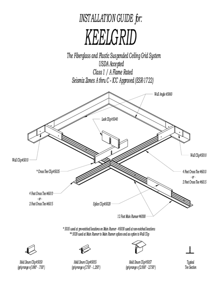
MAIN RUNNER INSTALLATION 1. Determine the center of the room on opposing walls. Check for room squareness and suitability of your layout. Mark location of Main Runners. 2. Determine position of first Cross Tee and cut off the starting Main Runners for proper Cross Tee notch alignment. 3. Install corrosive resistant hanger eyes and appropriate suspension wire along Main Runners. Typically 4’ on center or less. 4. Drill any additional hanging wire holes between 1st and 2nd ribs (approximately 9/16” down) of Main Runners. FIG. 1 5. Install wall clips at the starting end of Main Runners. They should rest on top of wall angle, and be securely attach to wall to prevent shifting during grid installation. FIG. 2 6. Install Wall Clips at terminating end of Main Runners. Attach to wall depending on local codes. FIG. 2 CROSS TEE INSTALLATION 1. Assemble the Cross Tees to the Main Runners using Cross Tee Clips. Use of Lock clips at these intersections helps assure a positive connection. The lock clip snaps onto the Main Runner. FIG. 3 2. Cut Cross Tees to length for the border area and install Wall Clips at the wall end. Attach to wall depending on local code. FIG. 2 PANEL INSTALLATION 1. Start installing the lay-in panels on one side of the room using the proper Hold-Down Clips. 2. Cut the border panels to fit their openings following the manufacturer’s recommendation. NOTES: 1. Light fixtures, air duct diffusers, etc. must be independently supported from the grid system. 2. Since fiberglass reinforced plastic has a coefficient of thermal expansion of 2.8 x 10⁻⁶ in./in./°F it is suggested to install the grid at the temperature at which the facility will operate. Consider leaving room for growth if the temperature is going to vary. Rev 509 READ ALL INSTRUCTIONS BEFORE BEGINNING INSTALLATION SAFETY PRECAUTIONS When power cutting, drilling or grinding fiberglass composite or other plastic materials, it is essential to wear protective clothing, such as goggles, filter masks, etc. PREPARATION 1. Measure your ceiling area. Lay out on the graph paper provided on the back page of this installation guide. 2. Main Runners are to be spaced 4’-0 1 /4” apart and Cross Tees are spaced 2’-01/8” apart for the standard 2’x4’ lay-in panels. FIG. 1 Consult with factory representative if other than standard lighting or panels are to be used. 3. Calculate the quantities of all the components you will need. See the front page of this installation guide for proper nomenclature. WALL ANGLE INSTALLATION 1. Determine the level of your ceiling. Allow proper clearance for overhead obstructions or grid installed accessories. 2. Once you have determined the ceiling height, install KEELGRID® wall angle at the desired height around the perimeter of the room. 3. Secure Wall Angles to walls with all plastic drive rivet or other noncorroding fasteners. FIG. 2 Rev 509 Rev 0509 Rev 0509 KEELGRID® INSTALLATION GUIDE SUPPLEMENT FOR SEISMIC ZONES A THROUGH C INDUSTRY STANDARDS Suspension and wall attachments requirements for metal ceiling suspension systems used primarily to support acoustical tile or acoustical lay-in panels should be followed with additions as noted below. Guidelines which cover these requirements are summarized in the Ceilings & Interior Systems Construction Association’s brochure, Guidelines for Seismic Restraint Direct Hung Suspended Ceiling Assemblies, Seismic ZONES 3&4, October 1, 1991. A similar brochure is available for ZONES 1&2. Other sources of information include: KEELGRID® SPLICES & INTERSECTION CONNECTORS 1. All splice and junction clips must be pop riveted with rivets having shear strength equal to or greater than 1/8th inch diameter stainless steel pop rivets. Back-up washers are to be used with the pop rivets. 2. One rivet on each side of the clip is to be installed. The rivet must be at least 1” in from the end of the clip. The rivet must be at least ½” inch down from the top of the tee web but no more than 3/4th inch down. This spacing places the rivet well below the top rib on the tee web but at or above the second rib down from the top of the web. 3. Both the cross tee clip (5035) and lock clip (5040) must be used and pop riveted. Splice clips (#5020) must be pop riveted when joining main runners. Keel Manufacturing, Inc. considers the configuration of the joined Cross Tee supports and the configuration of the Cross Tee supports to be its trademark. Rev 509 KEELGRID® Installation Guide – SUPPLEMENT The first page of the KEELGRID® installation guide shows the parts and part numbers. Main tees and cross tees are the same profile. A clip system is used to hold the Tees together. The vertical stem of the Tee has three ridges. The clips have corresponding groves. Main runners are joined by a 6” Splice Clip (#5020). Cross tees are held by an 8” Cross Tee Clip (#5035). The Cross Tee Clip straddles the main tees and clips to the cross tees on either side of the main. The Cross Tee Clip has a routered slot that corresponds to the pre-notched locations on the main runners. Four foot tees also are notched in the middle for construction of a 2x2 system. To lock the cross tees to the main runners, a 4” Lock Clip (#5040) is put on the main runners but across the Cross Tee Clip. The Lock Clip has a larger and deeper routered slot so it can fit across the Cross Tee clip. A Lock Clip is also used on a 4’ to 2’ junction in a 2x2 system. Cross Tees and Main runners butt up to the Wall Angle. A Splice Clip bridges from the Tee to the Angle. Note that this assembly is free to float. An option to anchor the Tee at the wall is to use a Wall Clip (#5010). The Wall Clip can be fastened to the T-bar and the wall. We usually quote one Wall Clip per run of main runners so the starting end of the run of mains can be fastened securely in place. Some customers don’t use Wall Clips at all. Some customers use Wall Clips around the entire perimeter of the room. Most Seismic Zone 3 & 4 installations require two adjacent walls to have the perimeter fastened. Wall Clips are more expensive then Splice Clips. KEELGRID® has a smaller net opening to the room than does a typical 9/16” or 15/16” grid spaced 48” on-center. A drawing shown on the back provides a layout detail for KEELGRID showing the on-center spacing and the net opening spacing. KEELGRID® is manufactured for a 48 ¼” on-center spacing of the mains. This “extra” ¼” provides room for the clips that hold the grid together and allows ceiling tiles to drop in place. Ceiling tiles are typically ¼” less than the nominal dimension (i.e. a 2’x4’ is 23 ¾” by 47 ¾”). Even though KEELGRID® is spaced 48 ¼” on-center, the net opening to the room is smaller than a 15/16” grid because the KEELGRID® face is 1 3/8”. Verify that any item that hangs below the grid or needs to swing down below the gridline is compatible with this smaller opening. KEELGRID’s net opening is 22 ¾” by 22 ¾” for a 2x2 system. For a 2x4 system, the opening is 22 ¾” by 46 7/8”. In a 4x4 layout the net opening is 46 7/8” by 46 7/8”. Particularly watch for diffusers that extend below the grid line or some trougher lights with swing-open doors for relamping. Most wet-location trougher light or clean room lights provide adequate swing door clearance. This issue seems to be more important in seismic zones 3 & 4 where lights and other ceiling equipment are often more tightly fastened in place and aren’t as free to move in the grid. With a 48 ¼” on-center spacing, the grid will “grow” relative to a 48” on-center grid. The KEELGRID® main runners are 144 ¾” long and are notched every 24 1/8” beginning 12 1/16” from the end. For a nominal 60 foot room with 5 mains in a run, KEELGRID® will be 5* ¾” = 9” longer than a grid based on a 48” on-center spacing. Watch sprinkler head placements and light fixture placements especially in very large areas. Rev 0509
