Using the Wiimote in Introductory Physics Experiments
advertisement

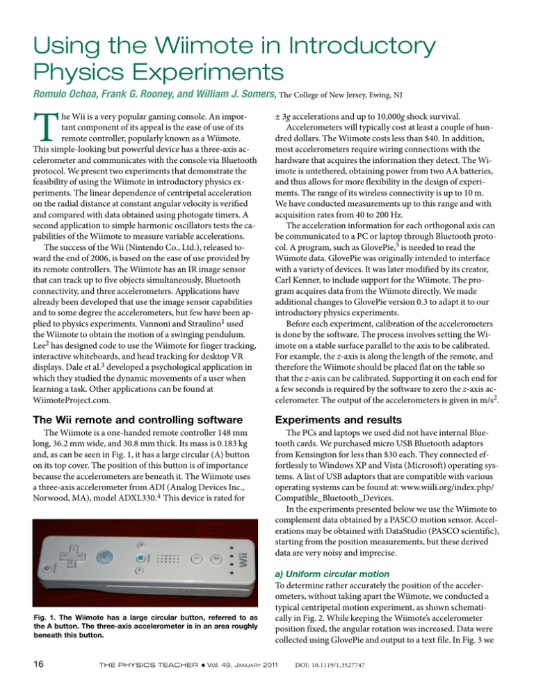
Using the Wiimote in Introductory Physics Experiments Romulo Ochoa, Frank G. Rooney, and William J. Somers, The College of New Jersey, Ewing, NJ T he Wii is a very popular gaming console. An important component of its appeal is the ease of use of its remote controller, popularly known as a Wiimote. This simple-looking but powerful device has a three-axis accelerometer and communicates with the console via Bluetooth protocol. We present two experiments that demonstrate the feasibility of using the Wiimote in introductory physics experiments. The linear dependence of centripetal acceleration on the radial distance at constant angular velocity is verified and compared with data obtained using photogate timers. A second application to simple harmonic oscillators tests the capabilities of the Wiimote to measure variable accelerations. The success of the Wii (Nintendo Co., Ltd.), released toward the end of 2006, is based on the ease of use provided by its remote controllers. The Wiimote has an IR image sensor that can track up to five objects simultaneously, Bluetooth connectivity, and three accelerometers. Applications have already been developed that use the image sensor capabilities and to some degree the accelerometers, but few have been applied to physics experiments. Vannoni and Straulino1 used the Wiimote to obtain the motion of a swinging pendulum. Lee2 has designed code to use the Wiimote for finger tracking, interactive whiteboards, and head tracking for desktop VR displays. Dale et al.3 developed a psychological application in which they studied the dynamic movements of a user when learning a task. Other applications can be found at WiimoteProject.com. ± 3g accelerations and up to 10,000g shock survival. Accelerometers will typically cost at least a couple of hundred dollars. The Wiimote costs less than $40. In addition, most accelerometers require wiring connections with the hardware that acquires the information they detect. The Wiimote is untethered, obtaining power from two AA batteries, and thus allows for more flexibility in the design of experiments. The range of its wireless connectivity is up to 10 m. We have conducted measurements up to this range and with acquisition rates from 40 to 200 Hz. The acceleration information for each orthogonal axis can be communicated to a PC or laptop through Bluetooth protocol. A program, such as GlovePie,5 is needed to read the Wiimote data. GlovePie was originally intended to interface with a variety of devices. It was later modified by its creator, Carl Kenner, to include support for the Wiimote. The program acquires data from the Wiimote directly. We made additional changes to GlovePie version 0.3 to adapt it to our introductory physics experiments. Before each experiment, calibration of the accelerometers is done by the software. The process involves setting the Wiimote on a stable surface parallel to the axis to be calibrated. For example, the z-axis is along the length of the remote, and therefore the Wiimote should be placed flat on the table so that the z-axis can be calibrated. Supporting it on each end for a few seconds is required by the software to zero the z-axis accelerometer. The output of the accelerometers is given in m/s2. The Wii remote and controlling software Experiments and results The Wiimote is a one-handed remote controller 148 mm long, 36.2 mm wide, and 30.8 mm thick. Its mass is 0.183 kg and, as can be seen in Fig. 1, it has a large circular (A) button on its top cover. The position of this button is of importance because the accelerometers are beneath it. The Wiimote uses a three-axis accelerometer from ADI (Analog Devices Inc., Norwood, MA), model ADXL330.4 This device is rated for The PCs and laptops we used did not have internal Bluetooth cards. We purchased micro USB Bluetooth adaptors from Kensington for less than $30 each. They connected effortlessly to Windows XP and Vista (Microsoft) operating systems. A list of USB adaptors that are compatible with various operating systems can be found at: www.wiili.org/index.php/ Compatible_Bluetooth_Devices. In the experiments presented below we use the Wiimote to complement data obtained by a PASCO motion sensor. Accelerations may be obtained with DataStudio (PASCO scientific), starting from the position measurements, but these derived data are very noisy and imprecise. Fig. 1. The Wiimote has a large circular button, referred to as the A button. The three-axis accelerometer is in an area roughly beneath this button. 16 a) Uniform circular motion To determine rather accurately the position of the accelerometers, without taking apart the Wiimote, we conducted a typical centripetal motion experiment, as shown schematically in Fig. 2. While keeping the Wiimote’s accelerometer position fixed, the angular rotation was increased. Data were collected using GlovePie and output to a text file. In Fig. 3 we The Physics Teacher ◆ Vol. 49, January 2011 DOI: 10.1119/1.3527747 50 Accelerometer locaon ac (m/s2) 40 Wiimote 30 20 10 Rotang plaorm 0 0 100 200 300 400 500 600 ω2 (rad/s) Photogate Fig. 2. Schematic diagram of the centripetal motion setup used to verify the Wiimote’s acceleration readings. The photogate measures the period of each rotation and is connected to a Science Workshop interface. Fig. 3. Centripetal acceleration measured by the Wiimote plotted as function of the square of its angular velocity. A best-fit line is shown whose slope was found to be 0.075 m and thus provides the location of the accelerometer’s chip. 50 b) Simple harmonic motion Another interesting yet simple application of the Wiimote is for the analysis of a vertically suspended oscillating spring with a mass attached. This system is well suited for these measurements since the changes in the acceleration have a sinusoidal time dependence. To verify the quality of the Wiimote’s measurements, a PASCO motion sensor was also used to follow the displacements of the oscillating mass. A simple harmonic oscillator’s position is given by: x = x0 sin(ω0 t + φ), where x0 is the initial amplitude, φ the phase angle that depends on the initial conditions, and ω0 = (k/m)1/2 the (1) ac (m/s2) 40 plot the centripetal acceleration measured by the Wiimote as a function of the square of the angular velocity, calculated from the period using a photogate. The quadratic dependence of centripetal acceleration is clearly shown. A linear regression curve is shown as a visual aid. The slope of this line is 0.075 m, indicating the distance of the accelerometer to the axis of rotation. Repeated experiments resulted in the localization of the accelerometers, roughly under the A button, with an uncertainty of about ± 0.005 m. Although a plot of the centripetal acceleration in terms of the period measured is instructive, it is not the best plot for obtaining regression parameters. We used the same setup to verify the linearity of the acceleration measurements that the Wiimote reports. Measurements were conducted at the same angular speed while varying the distance of the Wiimote to the axis of rotation. Figure 4 shows the centripetal acceleration calculated from the periods measured by a photogate and the values measured directly by the Wiimote. Uncertainties in the accelerations are less than 2% and are not visible due to the size of the symbols representing the data. The line shown is a fit to the calculated radial accelerations and is added as a visual aid. Although the Wiimote accelerometers are rated up to ± 3g, we obtained data up to 4g with small errors. 30 20 10 0 0.00 0.05 0.10 0.15 0.20 radius (m) Fig. 4. Graph of centripetal acceleration versus radius for the Wiimote (circles) calculated from photogate measurements. The uncertainty for the photogate data is smaller than the triangular symbols’ height. The straight line is a regression fit to the calcualted data. natural frequency. Taking second derivatives of Eq. (1) we obtain the acceleration as: a = -ω2 x0 sin(ω0 t + φ). (2) Figure 5 displays the acceleration-versus-time relation, obtained using the Wiimote with 40 data points captured per second. It clearly shows the expected sinusoidal time dependence. An initial displacement of 0.11 m was given to the system. The spring’s force constant was determined to be 7.30 ± 0.05 N/m and its mass 0.051 kg. An additional 0.130 kg were added to the Wiimote’s mass in the form of a cup (to support the remote) and a standard mass for increased linear stability of the system. Under these conditions a natural angular frequency of 4.7 ± 0.1 rad/s is calculated. The graph shows an acceleration amplitude of 2.5 ± 0.1 m/s2, which agrees well with the value calculated from using ω02x0. A period of 1.33 ± 0.02 s is obtained from this data. Figure 6 shows the timedependent position graph obtained using the motion sensor. At a 40-Hz collection rate, it is a very smooth curve. DataStudio uses differentiation algorithms to display the acceleration starting from the position curve. Although the positionversus-time graph obtained with the motion sensor was very smooth, Fig. 7 shows that the acceleration values are not close to those expected and the response is unreliable. The Physics Teacher ◆ Vol. 49, January 2011 17 Conclusions Fig. 5. Acceleration-versus-time graph obtained using the Wiimote. The remote was hung from a spring with a force constant of 7.30 N/m and given initial amplitude of 0.11 m. The data that we obtained from the experiments show that the Wiimote can be used as an inexpensive and accurate accelerometer in introductory physics experiments. The data from the uniform circular motion experiment show that the Wiimote is capable of giving accurate acceleration results within its stated range. Each data point that was produced by the Wiimote was within the error associated with the calculated acceleration. The Wiimote has the capability of enhancing some experiments or to easily obtain measurements that would be cumbersome to do with other devices. The Wiimote’s main strength, other than its low cost, is its coupling of three accelerometers with wireless communication. Carefully designed experiments can showcase the power of the device without reaching its limitations. We believe that the good agreement of the results with calculated values, and the ease of use of the Wiimote, make the techniques described suitable for introductory physics experiments and for demonstrations. The Wiimote offers students computerized data acquisition, relieving them of the sometimes tedious task of recording their data, while allowing them to devote more of their time to the setup, data analysis, and the thoughtful interpretation and comparison of their results with appropriate physical models. References Fig. 6. Position-versus-time graph obtained using a PASCO motion sensor at a 40-Hz acquisition rate. The sensor recorded the position of the Wiimote. 1. M. Vannoni and S. Straulino, “Low-cost accelerometers for physics experiments,” Eur. J. Phys. 28, 781–787 (2007). 2. johnnylee.net/projects/wii/. 3. R. Dale, J. Roche, K. Snyder, and R. McCall, “Exploring action dynamics as an index of paired-associate learning,” PLoS ONE 3(3), e1728. doi:10.1371/journal.pone.0001728 (2008); www. plosone.org/doi/pone.0001728. 4. www.analog.com/en/press-release/May_09_2006_ADI_ Nintendo_Collaboration/press.html. 5. carl.kenner.googlepages.com/. Romulo Ochoa is a professor of physics at The College of New Jersey. His research interests are in experimental condensed matter. He enjoys designing physics experiments for high school and undergraduate physics courses. Department of Physics, The College of New Jersey, Ewing, NJ 08628; ochoa@tcnj.edu Frank Rooney graduated from The College of New Jersey in the fall of 2010. rooney8@tcnj.edu Fig. 7. Acceleration-versus-time graph obtained from data captured using a PASCO motion sensor at a 40-Hz acquisition rate. The sensor recorded the position of the Wiimote. 18 The Physics Teacher ◆ Vol. 49, January 2011 William Somers received a BS degree in physics from The College of New Jersey and MS degree in electrical and computer engineering from Rutgers University. His research interests include nonlinear control and dynamics, artificial intelligence, and communication networks. WilliamJSomers@gmail.com


