Well Testing - Schlumberger
advertisement
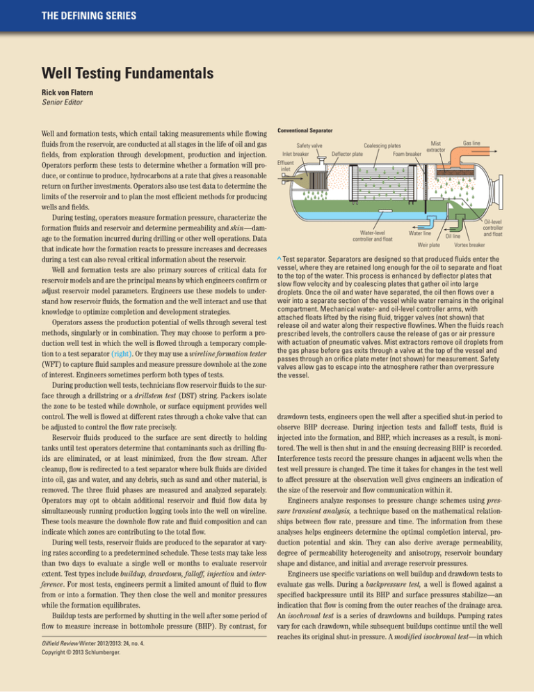
THE DEFINING SERIES Well Testing Fundamentals Rick von Flatern Senior Editor Well and formation tests, which entail taking measurements while flowing fluids from the reservoir, are conducted at all stages in the life of oil and gas fields, from exploration through development, production and injection. Operators perform these tests to determine whether a formation will produce, or continue to produce, hydrocarbons at a rate that gives a reasonable return on further investments. Operators also use test data to determine the limits of the reservoir and to plan the most efficient methods for producing wells and fields. During testing, operators measure formation pressure, characterize the formation fluids and reservoir and determine permeability and skin—damage to the formation incurred during drilling or other well operations. Data that indicate how the formation reacts to pressure increases and decreases during a test can also reveal critical information about the reservoir. Well and formation tests are also primary sources of critical data for reservoir models and are the principal means by which engineers confirm or adjust reservoir model parameters. Engineers use these models to understand how reservoir fluids, the formation and the well interact and use that knowledge to optimize completion and development strategies. Operators assess the production potential of wells through several test methods, singularly or in combination. They may choose to perform a production well test in which the well is flowed through a temporary completion to a test separator (right). Or they may use a wireline formation tester (WFT) to capture fluid samples and measure pressure downhole at the zone of interest. Engineers sometimes perform both types of tests. During production well tests, technicians flow reservoir fluids to the surface through a drillstring or a drillstem test (DST) string. Packers isolate the zone to be tested while downhole, or surface equipment provides well control. The well is flowed at different rates through a choke valve that can be adjusted to control the flow rate precisely. Reservoir fluids produced to the surface are sent directly to holding tanks until test operators determine that contaminants such as drilling fluids are eliminated, or at least minimized, from the flow stream. After cleanup, flow is redirected to a test separator where bulk fluids are divided into oil, gas and water, and any debris, such as sand and other material, is removed. The three fluid phases are measured and analyzed separately. Operators may opt to obtain additional reservoir and fluid flow data by simultaneously running production logging tools into the well on wireline. These tools measure the downhole flow rate and fluid composition and can indicate which zones are contributing to the total flow. During well tests, reservoir fluids are produced to the separator at varying rates according to a predetermined schedule. These tests may take less than two days to evaluate a single well or months to evaluate reservoir extent. Test types include buildup, drawdown, falloff, injection and interference. For most tests, engineers permit a limited amount of fluid to flow from or into a formation. They then close the well and monitor pressures while the formation equilibrates. Buildup tests are performed by shutting in the well after some period of flow to measure increase in bottomhole pressure (BHP). By contrast, for Oilfield Review Winter 2012/2013: 24, no. 4. Copyright © 2013 Schlumberger. Conventional Separator Safety valve Inlet breaker Deflector plate Gas line Mist Coalescing plates extractor Foam breaker Effluent inlet Water-level controller and float Water line Weir plate Oil line Oil-level controller and float Vortex breaker > Test separator. Separators are designed so that produced fluids enter the vessel, where they are retained long enough for the oil to separate and float to the top of the water. This process is enhanced by deflector plates that slow flow velocity and by coalescing plates that gather oil into large droplets. Once the oil and water have separated, the oil then flows over a weir into a separate section of the vessel while water remains in the original compartment. Mechanical water- and oil-level controller arms, with attached floats lifted by the rising fluid, trigger valves (not shown) that release oil and water along their respective flowlines. When the fluids reach prescribed levels, the controllers cause the release of gas or air pressure with actuation of pneumatic valves. Mist extractors remove oil droplets from the gas phase before gas exits through a valve at the top of the vessel and passes through an orifice plate meter (not shown) for measurement. Safety valves allow gas to escape into the atmosphere rather than overpressure the vessel. drawdown tests, engineers open the well after a specified shut-in period to observe BHP decrease. During injection tests and falloff tests, fluid is injected into the formation, and BHP, which increases as a result, is monitored. The well is then shut in and the ensuing decreasing BHP is recorded. Interference tests record the pressure changes in adjacent wells when the test well pressure is changed. The time it takes for changes in the test well to affect pressure at the observation well gives engineers an indication of the size of the reservoir and flow communication within it. Engineers analyze responses to pressure change schemes using pressure transient analysis, a technique based on the mathematical relationships between flow rate, pressure and time. The information from these analyses helps engineers determine the optimal completion interval, production potential and skin. They can also derive average permeability, degree of permeability heterogeneity and anisotropy, reservoir boundary shape and distance, and initial and average reservoir pressures. Engineers use specific variations on well buildup and drawdown tests to evaluate gas wells. During a backpressure test, a well is flowed against a specified backpressure until its BHP and surface pressures stabilize—an indication that flow is coming from the outer reaches of the drainage area. An isochronal test is a series of drawdowns and buildups. Pumping rates vary for each drawdown, while subsequent buildups continue until the well reaches its original shut-in pressure. A modified isochronal test—in which www.slb.com/defining Quartz pressure gauge Packer assembly Tool piston Probe Packer assembly piston > WFT sampling. Pistons are driven from one side of the WFT to force a packer assembly firmly against the formation to be tested. At its center, the packer includes a probe that is then extended into the formation to withdraw wellbore fluids. Formation fluids (red arrows) flow into the probe and into flowlines. The fluids are pumped into the wellbore until they are sufficiently free of contamination as determined by downhole fluid analysis (green and brown cylinders). Uncontaminated fluids are directed into storage bottles (orange) where the fluids are kept at in situ conditions. Multiple samples can be taken on one trip into the well. When all tests are completed, the samples are brought to the surface and may be sent to laboratories for advanced testing. A quartz pressure gauge measures and records bottomhole pressures. drawdown and buildup periods are of equal duration—may also be used. Based on data from these tests, engineers are able to determine production potential, skin and absolute open flow (AOF)—the theoretical rate at which the well would flow if backpressure on the sandface, or the borehole wall, were zero. Operators use AOF as the basis for calculations to determine the relationship between backpressure settings and flow rates of the well. Rather than use well tests, operators may opt to evaluate their wells using WFTs that include a quartz pressure gauge and a fluid sampling tool placed across a production interval (above). During these formation tests, reservoir fluids are pumped or flowed into the WFT through a probe inserted into the formation or between packers set above and below the sampling site. The reservoir fluids, which may be contaminated with drilling fluid, are first flowed or pumped through flowlines in the tool into the wellbore while the contamination level decreases. Once engineers determine that the formation is delivering minimally contaminated reservoir fluids, they redirect flow to sample chambers within the tool. The chambers are retrieved to the surface and transported to laboratories for analysis. Scientists also use downhole fluid analysis (DFA) to monitor the sampling process. Using optical spectroscopy, or the recorded light spectrum, engineers identify in real time the composition of fluids as they flow into the tool; this method also reveals critical data about the reservoir without waiting for laboratory tests to be completed. Additionally, the DFA measurements confirm that the sample is uncontaminated and eliminate uncertainties associated with fluid transport and laboratory reconstruction of in situ conditions necessary for fluid analysis. Technicians also use DFA data to identify gas/oil ratios, relative asphaltene content and water fraction in real time. A variety of well and formation test schemes are performed throughout the stages in the life of a well or field. At the exploration stage, operators may use well tests to simulate production after a well is completed to establish production potential and reserves estimates. In addition, capturing large fluid samples at the surface gives experts an opportunity to perform laboratory measurements on the reservoir fluids. Well tests at the exploration stage also allow operators to determine if low flow rates are affected by skin or are the result of natural permeability of the reservoir. Armed with the knowledge of either situation, engineers can then take appropriate actions, plan treatments that may be necessary once production commences or decide to abandon the project for economic reasons. For instance, well tests can be used to estimate reservoir size, which allows operators to abandon a small reservoir that will not be economical despite high initial flow rates. During the field development stage, well tests help indicate wells that may require stimulation treatments. Using well test data, engineers predict induced or natural fracture length and conductivity. They can then estimate productivity gains that may be realized from a stimulation treatment. In addition, WFTs can be used for pressure testing to determine static reservoir pressures and to confirm fluid contacts and density gradients. This information helps analyze communication within the reservoir, tie reservoir characteristics to a geologic model and identify depleted zones. During the production phase, well tests are aimed at monitoring reservoirs, collecting data for history matching—comparing actual production with predicted production from reservoir simulators—and assessing the need for stimulation. These tests use a pressure gauge placed at formation depth to collect data during pressure buildup and drawdown. Well productivity usually diminishes over time, sometimes as a result of formation damage from fines migration—the movement of very small particles through the formation to the wellbore where they fill pore spaces and reduce permeability. Engineers may perform formation tests to predict the likely effectiveness of treatments to remove these fines. The effects of completion choices may also be assessed using formation tests to aid engineers in planning required remedial operations. Well and formation test data provide operators with information about their new and producing wells that is critical to making near-term operational decisions. But the real power of well test data is their application to construction or correction of reservoir models, which allow operators to make better long-term decisions about their assets. Oilfield Review
