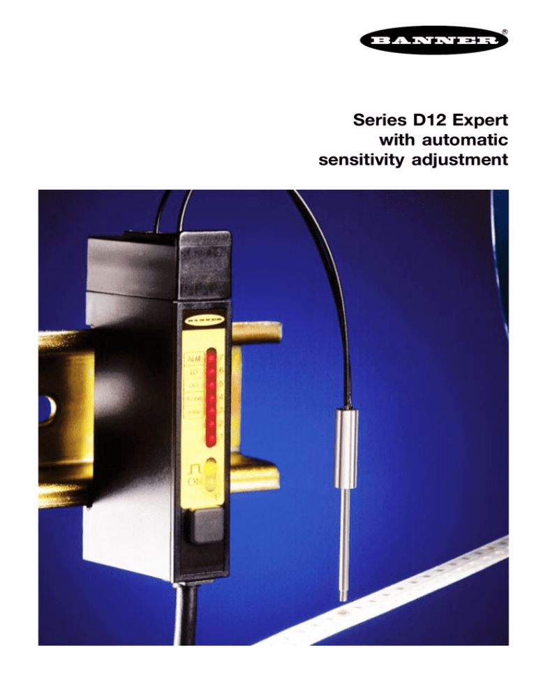
Series D12 Expert with automatic sensitivity adjustment
advertisement

R Series D12 Expert with automatic sensitivity adjustment Series D12 Expert with automatic sensitivity adjustment ● Sensor for glass- or plastic fibre-optics ● Automatic sensitivity adjustment with external switch or PLC ● Extremely high excess gain, but also reliable detection of low sensing contrast ● Switching frequency 2500 Hz ● Visible red light ● Switchable off-delay and light-/dark operation ● 7-segment LED bargraph display for excess gain and sensing contrast indication ● Alarm output indicating low excess gain ● DIN-rail mounting By the simple push of a button, the D12 Expert adapts itself to each specific sensing application. A microprocessor is used in the programming of the switch point and hysteresis. This makes the D12 Expert the ideal sensor for low contrast applications and applications that require extremely high excess gain. The programming of the D12 Expert is very simple yet secure. The user accesses the program mode by a sequence of holding and clicking the push-button. The user then presents the two detection conditions. In each condition, the button is pressed once and the sensor then automatically finds the optimum switching point and contrast. Immediately after programming, the sensing contrast is displayed by the flashing three times of between one to seven LED’s. This allows the user to assess during installation how reliable the sensor will be during actual operation. Three or more LED’s flashing (moderate contrast) is recommended for harsh industrial environments. However, low sensing contrast can often be improved by changing the distance between the sensor and the object or by repositioning the sensor. Sensing contrast should be high (6+ LED’s) under very harsh environmental or changing conditions (i.e., sensor to object distance). The sensor retains its programming even with power removed until reprogrammed. During operation a 7-segment LED bargraph provides an accurate display of the excess gain. Immediately after programming, the excess gain should be high enough to compensate for signal loss due to the gradual contamination of the lens that is likely to occur in any application. During operation, the 7-segment bargraph continuously provides an indication of the gradual decrease in excess gain. An alarm indicator LED and an alarm output give warning of a marginal sensing condition before the sensor actually fails. D12 Expert applications Sensing of the perforations in a continuous web of clear plastic bags. Determination if a surface mount IC is improperly placed in a plastic pocket. A remote programming wire allows programming with an external switch or PLC. This allows a PLC to adapt the sensor automatically to the actual sensing conditions such as changing the sensing object. As well as adjustment of the switching point, the programming button of the D12 Expert also allows you to toggle between either “no delay” or a 40 millisecond pulse stretcher and between light and dark operate. R Wave length Red Adjustment (with push-button or external) Supply Supply voltage Ripple Vpp No load current Dimensions [mm] Protection 12 30 35.5 5 70 64 26 20 680 nm light/dark operate sensitivity (automatic) 40 ms off-delay 10...30 VDC 10 % ≤ 45 mA short-circuit (pulsed) reverse polarity Output Continuous load current Switching frequency ≤ 150 mA 2500 Hz Material Housing Cover Protection class (DIN 40050) Temperature range Cable ABS acrylic IP 66 -20…+70 °C 2 m, PVC 5 x 0.34 mm2 Indicator LEDs Green Green flashing Yellow 7-segment red bargraph display power-on programming mode output load status signal strength, programming LEDs Front view with indicator LEDs ALM 7 LO 6 DO 5 40 ms 4 0 ms 3 2 1 ON 7-segment LED bargraph display indicating : – signal strength – contrast – program status – alerts LEDs indicating – output – power-on programming button Accessories Brackets SMBD12 Wiring through-hole mounting (included) BN BK WH GR BU + 1) 2) – 1) Alarm 2) External programming cable Detection mode with typical fibre-optic 1) Opposed Diffuse with with with with IT13S IT23S BT13S BT23S numb er Ident Type Conn ectio n ut Outp Light Max. rang sourc e e Photoelectric sensors Series D12 Expert with automatic sensitivity adjustment for glass fibre-optics 442 930 68 178 mm mm mm mm red pnp cable D12-EP6-FV 30 419 68 for plastic fibre-optics Opposed Diffuse with with with with PIT26U PIT46U PBT26U PBT46U 84 mm 315 mm 25 mm 95 mm red pnp cable D12-EP6-FP 30 419 65 Programming of the D12 Expert Programming of the output From the RUN mode the D12 Expert has three programming modes : Push-button Mode/function Indicator LEDs holding down button (2 s) from RUN to OCD „LO“/„DO“ and „40 ms“/„0 ms“ active triple-click goes into OCP „0 ms“/ „40 ms“ flashes single-click off-delay on/off toggles between „0 ms“ and „40 ms“ double-click OCP „LO“/„DO“ flashes single-click changes into light-/dark operate toggles between „LO“ and „DO“ double-click goes to RUN bargraph (red LEDs) indicates light strength The TEACH mode optimizes the sensitivity adjustment of the sensor. After this adjustment the sensor automatically goes into the RUN mode. The OUTPUT CONFIGURATION DISPLAY (OCD) indicates the actual output programming : light- and dark operate (LED „LO“ or LED „DO“) and off-delay (LED “0 ms“ or “40 ms“). The sensor leaves the OCD mode automatically after 10 seconds, when no adjustments have been made during this period. The OUTPUT CONFIGURATION PROGRAM (OCP) allows you to toggle between either light-operate and dark- operate and to program the off-delay to 0 ms or 40 ms. The sensor leaves the OCP mode automatically after 90 seconds, when no adjustments have been made during this period. Contrast indication Flashing LEDs 1 1…2 1…3 1…4 1…5 1…6 1…7 1 Contrast unacceptable low moderate good very good high very high ) A wide range of glass- and plastic fibre-optics can be found in the Photoelectric Catalogue. Automatic sensitivity adjustments Push-button Mode/function Indicator LEDs holding down button (2 s) from RUN to OCD „LO“/„DO“ and „40 ms“/„0 ms“ active double-click goes to TEACH green LED flashes single-click TEACH condition 1 detection of the first sensing condition bargraph (red LEDs) run through 1x, green LED flashes twice single-click TEACH condition 2 detection of the second sensing condition bargraph (red LEDs) run through 1x, bargraph (red LEDs) indicates the obtained contrast (see table) Subject to changes without notice • Edition 11.98/1 P/N ED009K8A ! IMPORTANT SAFETY WARNING ! These sensors do NOT include the self-checking redundant circuitry necessary to allow their use in personnel safety applications. A sensor failure or malfunction can result in either an energised or deenergised output condition. These products should not be used as sensing devices for personnel safety.


