Filtering
advertisement

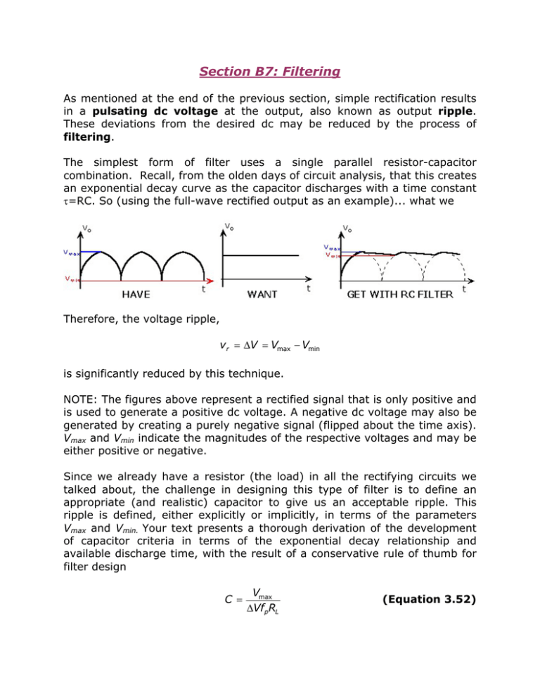
Section B7: Filtering As mentioned at the end of the previous section, simple rectification results in a pulsating dc voltage at the output, also known as output ripple. These deviations from the desired dc may be reduced by the process of filtering. The simplest form of filter uses a single parallel resistor-capacitor combination. Recall, from the olden days of circuit analysis, that this creates an exponential decay curve as the capacitor discharges with a time constant τ=RC. So (using the full-wave rectified output as an example)... what we Therefore, the voltage ripple, vr = ∆V = Vmax − Vmin is significantly reduced by this technique. NOTE: The figures above represent a rectified signal that is only positive and is used to generate a positive dc voltage. A negative dc voltage may also be generated by creating a purely negative signal (flipped about the time axis). Vmax and Vmin indicate the magnitudes of the respective voltages and may be either positive or negative. Since we already have a resistor (the load) in all the rectifying circuits we talked about, the challenge in designing this type of filter is to define an appropriate (and realistic) capacitor to give us an acceptable ripple. This ripple is defined, either explicitly or implicitly, in terms of the parameters Vmax and Vmin. Your text presents a thorough derivation of the development of capacitor criteria in terms of the exponential decay relationship and available discharge time, with the result of a conservative rule of thumb for filter design C = Vmax ∆VfpRL (Equation 3.52) where: Vmax is the maximum voltage magnitude of the rectified signal (positive or negative) ∆V is the ripple (Vmax-Vmin) RL is the load resistor fp is the output fundamental frequency. It’s worthwhile to take a minute on this last term. The output fundamental frequency is simply the number of pulses per second of the rectified output. For half-wave rectification, this is simply the frequency of the input signal (where we’ve just chopped off half of the waveform), but for full-wave rectification this term is double the original frequency (flipped part of the original sinusoid so that everything’s on the same side). Specifically, for a 60-Hz input: fp=60 Hz for half-wave rectification fp=120 Hz for full-wave rectification A note of caution (from one who has been caught many times) -- be careful what numbers you slap in an equation! Equation 3.52 provides a solid estimate of the capacitance required for a given circumstance, but a factor of 2 makes a difference! Just a couple more relationships that you may want to make note of: ¾ The rms (root-mean-square) ripple voltage, Vr(rms) is derived by approximating the average of the ripple as ∆V/2 and the shape of the filtered waveform as a sawtooth, or Vr (rms) = Vmax − Vmin 2 3 (Equation 3.54) ¾ The ripple factor is defined as the ratio of the rms ripple voltage to the dc voltage desired. Ideally, this term would be zero (i.e., no ripple), but practically, this may be another design constraint to satisfy. ripple factor = Vr (rms) Vdc (Equation 3.55)


