A HARMONICS PRIMER - Hawaiian Electric
advertisement

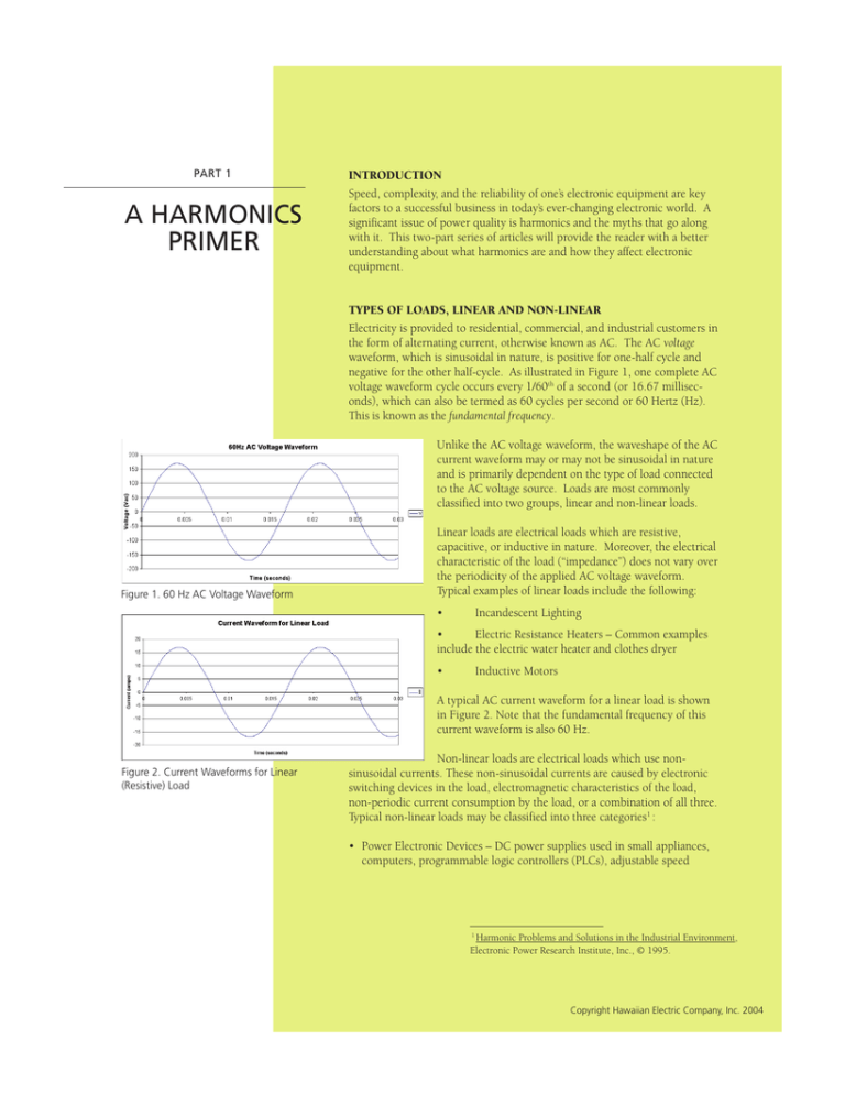
PART 1 A HARMONICS PRIMER INTRODUCTION Speed, complexity, and the reliability of one’s electronic equipment are key factors to a successful business in today’s ever-changing electronic world. A significant issue of power quality is harmonics and the myths that go along with it. This two-part series of articles will provide the reader with a better understanding about what harmonics are and how they affect electronic equipment. TYPES OF LOADS, LINEAR AND NON-LINEAR Electricity is provided to residential, commercial, and industrial customers in the form of alternating current, otherwise known as AC. The AC voltage waveform, which is sinusoidal in nature, is positive for one-half cycle and negative for the other half-cycle. As illustrated in Figure 1, one complete AC voltage waveform cycle occurs every 1/60th of a second (or 16.67 milliseconds), which can also be termed as 60 cycles per second or 60 Hertz (Hz). This is known as the fundamental frequency. Unlike the AC voltage waveform, the waveshape of the AC current waveform may or may not be sinusoidal in nature and is primarily dependent on the type of load connected to the AC voltage source. Loads are most commonly classified into two groups, linear and non-linear loads. Figure 1. 60 Hz AC Voltage Waveform Linear loads are electrical loads which are resistive, capacitive, or inductive in nature. Moreover, the electrical characteristic of the load (“impedance”) does not vary over the periodicity of the applied AC voltage waveform. Typical examples of linear loads include the following: • Incandescent Lighting • Electric Resistance Heaters – Common examples include the electric water heater and clothes dryer • Inductive Motors A typical AC current waveform for a linear load is shown in Figure 2. Note that the fundamental frequency of this current waveform is also 60 Hz. Figure 2. Current Waveforms for Linear (Resistive) Load Non-linear loads are electrical loads which use nonsinusoidal currents. These non-sinusoidal currents are caused by electronic switching devices in the load, electromagnetic characteristics of the load, non-periodic current consumption by the load, or a combination of all three. Typical non-linear loads may be classified into three categories1 : • Power Electronic Devices – DC power supplies used in small appliances, computers, programmable logic controllers (PLCs), adjustable speed 1 Harmonic Problems and Solutions in the Industrial Environment, Electronic Power Research Institute, Inc., © 1995. Copyright Hawaiian Electric Company, Inc. 2004 PART 1 A Harmonics Primer drives, and just about any electronic device requiring rectified DC voltage for power. This category of equipment is the largest contributor to harmonics and also the most sensitive to harmonic distortion. • Saturable or Ferromagnetic Devices – Typically transformers, which produce harmonics due to the excitation hysteresis. These harmonics are usually small unless the transformer is over-excited due to conditions where the applied voltage exceeds the transformer rating. • Arcing Devices – Most common are fluorescent lamps, especially large high intensity discharge (HID) lamps. Other types of devices include arc furnaces or arc welders. An example of an AC current waveform for a non-linear load is shown in Figure 3. Figure 3. Current Waveform for Non-Linear Load Figure 4. Resolution of Non-Sinusoidal Current Waveform into Harmonic Components HARMONICS… WHAT ARE THEY AND HOW ARE THEY QUANTIFIED? A harmonic, whether voltage or current, is a sinusoidal waveform whose frequency is an integer multiple of the fundamental frequency. As noted above, the fundamental frequency of the supplied AC voltage waveform is 60 Hz. Hence, the 3rd harmonic has a frequency = 3 x 60 Hz = 180 Hz, the 5th harmonic has a frequency = 5 x 60 Hz = 300 Hz, and so on. It can be shown that any voltage or current waveform, either sinusoidal or non-sinusoidal, can be resolved into its harmonic components (also known as “orders”) with varying magnitude and phase. This is graphically demonstrated in Figure 4. At any point in time in the graph, it can easily be shown that Isum = I1 + I3 + I5, or that the magnitude of the non-sinusoidal current waveform is the sum of its harmonic components. It is important to note that the vast majority of harmonic currents found in a distribution system are odd-order harmonics (3rd, 5th, 7th, etc.). More often than not, the sources of the harmonic currents in a distribution system are the loads in operation within that facility. Interestingly, these are frequently the types of loads that are the most sensitive to distortion in the current and/or voltage. Voltage distortion (i.e., deviation from the pure sinusoidal waveshape), is generated indirectly as a result of harmonic currents flowing through a distribution system. Excessive harmonic current can produce distorted voltage drops in the power source impedance. A measure of harmonic content has been defined as Total Harmonic Distortion, or THD. THD is calculated by taking the square root of the sum of the squares of all harmonics above the fundamental and dividing by the fundamental amplitude. This value is then multiplied by 100% to yield a percent- Copyright Hawaiian Electric Company, Inc. 2004 PART 1 A Harmonics Primer age. For instance, if the fundamental amplitude is 120 volts, the 3rd harmonic amplitude is 20 volts, and the 5th harmonic amplitude is 15 volts, the voltage THD can be calculated as follows: THDvoltage(%) = √20 + 15 x 100% = 20.8% 120 2 2 PROBLEMS DUE TO HARMONICS An observed characteristic of harmonic currents in a typical building distribution system is that odd-ordered harmonics (i.e., the 3rd, 5th, 7th, etc.) are usually larger in amplitude than even-ordered harmonics. Another observed effect is that single-phase non-linear loads, such as power electronic devices, tend to produce harmonic currents that are predominantly triplen or multiples of 3 (i.e., 3rd, 6th, 9th, etc.). These triplen harmonics, especially the 3rd, tend to amplify in the shared neutral conductor of 3-phase 4-wire systems. Typical problems caused by high current and voltage harmonics include2: • Resonant interaction with capacitor banks that can lead to overheating and premature failure. • Overloading of conductors and transformers. • Overheating of distribution system equipment (bus bars, lugs, and conductor insulation). • Harmonic fluxes in motors that lead to decreased efficiency, heating, and excessive vibration. • Nuisance tripping of molded-case electronic circuit breakers that sense peak current. • Zero-crossing synchronization problems with devices such as digital clocks. POWER QUALITY STANDARDS RELEVANT TO HARMONICS The following IEEE Standards apply to recommended levels of harmonic distortion: IEEE 519-1992 establishes guidelines and recommended practices for customers and utilities to control harmonic distortion levels. It also recommends a limit of 5% voltage harmonic distortion on general purpose systems. ANSI/IEEE STD-519 provides guidelines for control of harmonic current and voltage. ANSI/IEEE STD-929 covers interconnection practices for photovoltaic power systems, including harmonic control. 2 Power Quality for Electrical Contractors Application Guide Vol. 1: Power Quality Fundamentals, Power Research Institute, Inc., Final Report February 1999.. Copyright Hawaiian Electric Company, Inc. 2004


