Basic Knowledge - Electrical Engineering in Refrigeration
advertisement
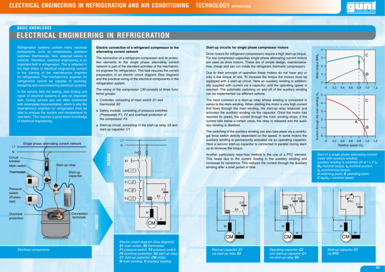
ELECTRICAL ENGINEERING IN REFRIGERATION AND AIR CONDITIONING TECHNOLOGY INTRODUCTION BASIC KNOWLEDGE ELECTRICAL ENGINEERING IN REFRIGERATION In the service field the testing, fault finding and repair of electrical systems is also an important item. During service you are often confronted with incomplete documentation, which is why the mechatronics engineer for refrigeration must be able to analyse the system and comprehend its operation. This requires a good basic knowledge of electrical engineering. Start-up circuits for single phase compressor motors The connection of a refrigerant compressor and its protective elements to the single phase alternating current network is part of the standard activities of the mechatronics engineer for refrigeration. This task requires the correct preparation of an electric circuit diagram (flow diagram) and the practical wiring of the electrical components in the refrigeration system. The wiring of the compressor CM M consists of three functional groups: Controller, consisting of main switch S1 and thermostat S2 Safety module, consisting of pressure switches (Pressostat) F1, F2 and overheat protection of the compressor F3 Start-up circuit, consisting of the start-up relay S3 3 and start-up capacitor C1 Single phase alternating current network Thermostat at Start-up relay Due to their principle of operation these motors do not have any or only a low torque at rest. To increase the torque the motors must be equipped with a start-up circuit. Here an auxiliary winding is additionally supplied with current via a capacitor until the operating speed is reached. The automatic switching on and off of the auxiliary winding can be implemented via different options. The most common is a start-up relay whose winding is connected in series to the main winding. When starting the motor a very high current first flows through the main winding, the start-up relay responds and activates the auxiliary winding via the capacitor. Once the motor has reached its speed, the current through the main winding drops. If the current falls below a certain value, the relay is released and the auxiliary winding is disabled. The switching of the auxiliary winding can also take place via a centrifugal force switch directly dependent on the speed. In some motors the auxiliary winding is permanently activated via an operating capacitor. Here a second start-up capacitor is connected in parallel during startup to increase the torque. Another particularly wear-free method is the use of a PTC element. This heats due to the current flowing in the auxiliary winding and increases its resistance. This reduces the current through the auxiliary winding after a brief period of time. DESIGN Circuit breaker Main switch Drive motors for refrigerant compressors require a high start-up torque. For low compressor capacities single phase alternating current motors are used as drive motors. These are of simple design, maintenancefree, cheap and can run inside the refrigerant (hermetic compressor). Start-up capacitor C Motor torque M/MN alternating current network Current through the main winding l/lN Refrigeration systems contain many electrical components, such as compressors, pressure switches, thermostats, fans, solenoid valves or controls. Therefore, electrical engineering is an important field in refrigeration. This is reflected in the high share of electrical engineering content in the training of the mechatronics engineer for refrigeration. The mechatronics engineer for refrigeration should be capable of planning, designing and commissioning electrical systems. B C A B Relative speed n/ns Start of a single phase alternating current motor with auxiliary winding: auxiliary winding is switched off at I = 2 IN MN nominal torque, IN nominal current, ns synchronous torque, A switching point, B operating point, C nN /ns = nominal speed Overheat protection Electrical components Connection C t terminals ANALYSE Pressure switch (Pressostat) Electric circuit diagram (flow diagram): S1 main switch, S2 thermostat, F1 pressure switch, F2 pressure switch, F3 overheat protection, S3 start-up relay, C1 start-up capacitor, CM motor, M main winding, H auxiliary winding Start-up capacitor C1 via start-up relay S3 Operating capacitor C2 and start-up capacitor C1 via start-up relay S3 Start-up capacitor C1 via PTC 207
