Q125 Signal Processor
advertisement

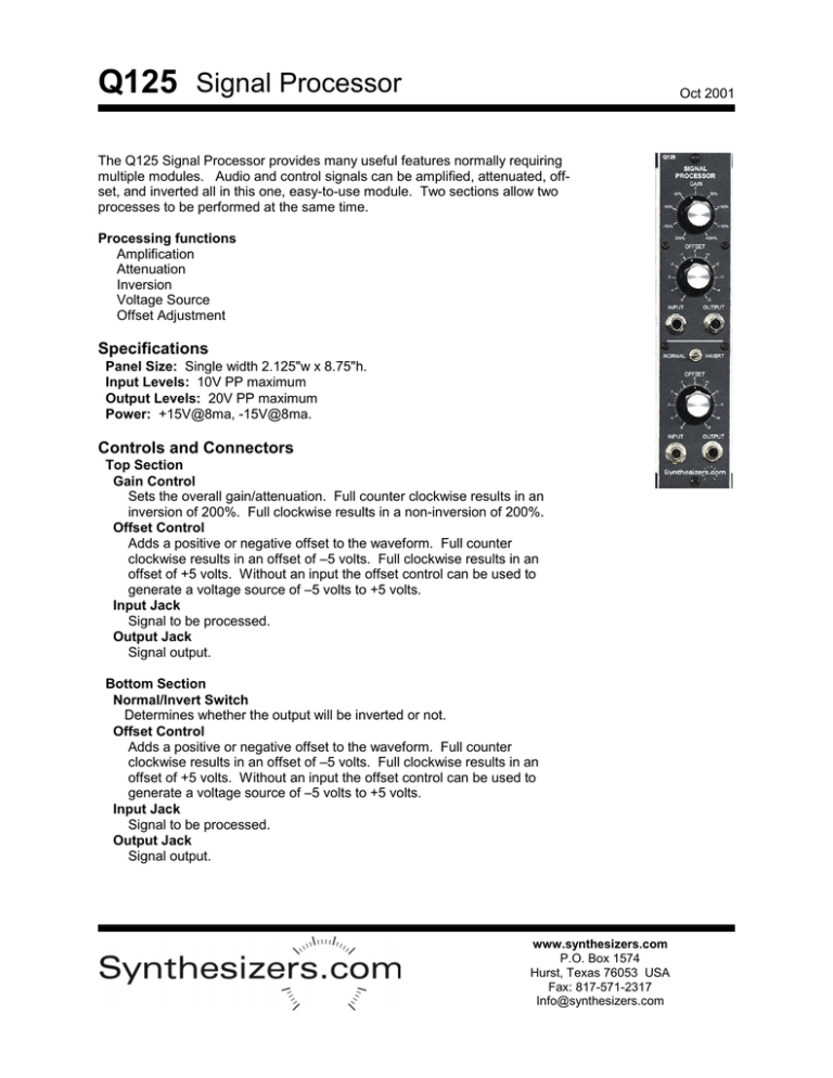
Q125 Signal Processor Oct 2001 The Q125 Signal Processor provides many useful features normally requiring multiple modules. Audio and control signals can be amplified, attenuated, offset, and inverted all in this one, easy-to-use module. Two sections allow two processes to be performed at the same time. Processing functions Amplification Attenuation Inversion Voltage Source Offset Adjustment Specifications Panel Size: Single width 2.125"w x 8.75"h. Input Levels: 10V PP maximum Output Levels: 20V PP maximum Power: +15V@8ma, -15V@8ma. Controls and Connectors Top Section Gain Control Sets the overall gain/attenuation. Full counter clockwise results in an inversion of 200%. Full clockwise results in a non-inversion of 200%. Offset Control Adds a positive or negative offset to the waveform. Full counter clockwise results in an offset of –5 volts. Full clockwise results in an offset of +5 volts. Without an input the offset control can be used to generate a voltage source of –5 volts to +5 volts. Input Jack Signal to be processed. Output Jack Signal output. Bottom Section Normal/Invert Switch Determines whether the output will be inverted or not. Offset Control Adds a positive or negative offset to the waveform. Full counter clockwise results in an offset of –5 volts. Full clockwise results in an offset of +5 volts. Without an input the offset control can be used to generate a voltage source of –5 volts to +5 volts. Input Jack Signal to be processed. Output Jack Signal output. www.synthesizers.com P.O. Box 1574 Hurst, Texas 76053 USA Fax: 817-571-2317 Info@synthesizers.com Q125 Signal Processor Testing No calibration is required on this module. Jumpers on the PC Board select +/-100% (jumper off) maximum gain or +/-200% (jumper on) maximum gain for each section. Normally the top section will provide +/-200% and the bottom section +/-100%. Top Section 1. Attach a volt meter to the output jack. 2. When the offset control is in it’s full counter-clockwise position, the output should be –5 volts. 3. When the offset control is in it’s full clockwise position, the output should be +5 volts. 4. Set the offset control to it’s center position (0 offset). 5. Apply a +5 volt to the input jack. 6. The output should be +10 volts when the gain control is in the full clockwise position and –10 volts when in the full counter-clockwise position. Bottom Section Same as the top section except the toggle switch selects between +100% gain and –100% gain. Oct 2001 Power Connector 6 pin .1” MTA type connector made by AMP. Available from Mouser Electronics or Digi-Key. Modules have a male PCB mount connector and cable harnesses have a female. Part Numbers: Female cable mount: #6404416 Male PCB mount: #6404566 Pinout: 1 = +15v 2 = key (pin removed) 3 = +5v 4 = gnd 5 = -15v Not all voltages are used on all modules. PC Board Layout www.synthesizers.com P.O. Box 1574 Hurst, Texas 76053 USA Fax: 817-571-2317 Info@synthesizers.com


